Installation – Lincoln Electric IM10046 VRTEX 360 User Manual
Page 16
A-6
INSTALLATION
VRTEX
®
360
A-6
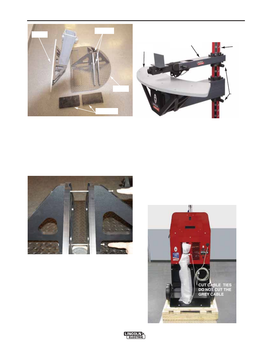
TABLE & SWING ARM SET-UP:
1. Place counter weights on base.
2. Using the 3/16” (4.8 mm) allen wrench, remove the
two 1/4” x 20 Allen-head screws from the base
assembly.
NOTE: The longer screw is in the top.
3. Insert red post into base assembly aligning the flat
on the pole with the hole.
NOTE: The post will only insert one way.
4. Using the 3/16” (4.8 mm) allen wrench, secure the
post into position by replacing and tightening the
screws.
6. Insert one of the pins into the post at the #6 loca-
tion.
7. From the top, slide the table onto the post letting it
rest on the pin inserted in previous step.
8. Insert the second pin into the post at the #13 posi-
tion.
9. Obtain the swing-arm from the rear of the VRTEX
®
360
by removing the cable ties from the swing arm
and cable. Grey cable should remain connected to
the VRTEX
®
360
(DO NOT CUT THE GREY
CABLE!).
Pins
5. Obtain the three post T pins from the factory pack-
aging of the VRTEX
®
360
.
Swing Arm
Table
Post
Table
Weights
Base
Screws
- Invertec V310-T DC (2 pages)
- VANTAGE 500 (CE) 11575 (50 pages)
- INVERTEC V350-PRO SVM152-A (155 pages)
- IMVERTEC V160-T (36 pages)
- IDEALARC CV-300 (112 pages)
- INVERTEC POWER WAVE 450 SVM112-B (293 pages)
- AUTO-DARKENING HELMET IM10001 (12 pages)
- IM10111 IDEALARC R3R-500-I (28 pages)
- IM10110 IDEALARC R3R-400 (25 pages)
- IM10051 INVERTEC V311-T AC_DC (38 pages)
- IM10059 SQUARE WAVE TIG 175 (30 pages)
- IM10096 POWER MIG 256 (37 pages)
- IM10096 POWER MIG 256 (38 pages)
- IM10105 POWER MIG 350MP (47 pages)
- IM10115 FLEXTEC 650 (42 pages)
- IM10132 FLEXTEC 650 (56 pages)
- IM10132 FLEXTEC 650 (36 pages)
- IM10018 IDEALARC DC-600 VRD (55 pages)
- IM10107 IDEALARC DC-400 (40 pages)
- IM10062 FLEXTEC 450 (72 pages)
- IM10091 FLEXTEC 450 CE (40 pages)
- IM10094 RED-D-ARC FX450 (31 pages)
- IM10157 12_24V 10A Auto HF Household Charger (16 pages)
- IM10139 JUMP STARTER (12 pages)
- IM10149 POWER WAVE ADVANCED MODULE (46 pages)
- IM10102 AIR VANTAGE 650 (60 pages)
- IM10103 AIR VANTAGE 700 (AU) (57 pages)
- IM10065 AIR VANTAGE 500 CUMMINS (54 pages)
- IM10066 AIR VANTAGE 500 (AU) (56 pages)
- IM10041 VANTAGE 500 CUMMINS (56 pages)
- IM10128 AIR VANTAGE 500 KUBOTA (AU) (56 pages)
- IM10090 ARC TRACKER (48 pages)
- IM10147 AUTO-DARKENING HELMET (12 pages)
- IM10087 AutoDrive 19 CONTROLLER (28 pages)
- IM10125 AutoDrive 19 TANDEM (34 pages)
- IM10069 AutoDrive 4R100 (32 pages)
- IM10145 AUTOPRO 20 (24 pages)
- IM10025 BIG RED 500 (40 pages)
- IM10019 BIG RED 600 (41 pages)
- IM10005 BULLDOG 140 (46 pages)
- IM10074 BULLDOG 5500 (56 pages)
- IM10067 CENTURY AC120 (20 pages)
- IM10109 CIRCULATOR (33 pages)
- IM10109 CIRCULATOR (36 pages)
- IM10153 CLASSIC 300 HE (60 pages)