Installation – Lincoln Electric IM10046 VRTEX 360 User Manual
Page 15
A-5
INSTALLATION
VRTEX
®
360
A-5
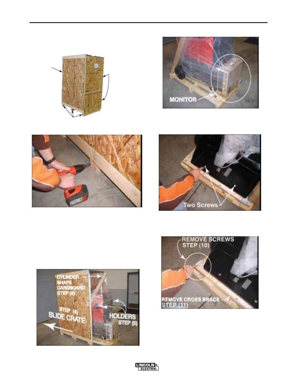
10. Remove the four screws from the wooden rear
cross brace.
11. Remove the wooden cross brace while ensuring
the unit is steady and secure.
12. Carefully roll the machine off the rear of the skid.
Ramping may be required.
13. Uncrate and unpack the table and table base.
3/8” BOLTS
REMOVE
FRONT PANELS
STEP (2)
DO NOT
REMOVE
REAR PANEL
FRONT
(upper)
FRONT
(lower)
9. Using the 3/8” wrench, remove the two screws from
the rear base securing the unit to the wooden crate.
7. Carefully cut and remove plastic wrapping.
8. Remove the monitor from the front of the machine.
4. Carefully slide the crate assembly from the
VRTEX
®
360.
5. Slide towards the rear of the machine. Be careful to
avoid damaging the welding device holders located
on each side of the machine.
6. Carefully remove the post (long cylinder-shaped
cardboard) from the crate.
3. Remove the six 3/8” bolts (three on each side) from
the bottom of the crate assembly.
2. Using the 3/8” (9.5 mm) wrench, remove the screws
from the upper and lower front panels on the ship-
ping crate.
NOTE: Do not remove rear panel.
- Invertec V310-T DC (2 pages)
- VANTAGE 500 (CE) 11575 (50 pages)
- INVERTEC V350-PRO SVM152-A (155 pages)
- IMVERTEC V160-T (36 pages)
- IDEALARC CV-300 (112 pages)
- INVERTEC POWER WAVE 450 SVM112-B (293 pages)
- AUTO-DARKENING HELMET IM10001 (12 pages)
- IM10111 IDEALARC R3R-500-I (28 pages)
- IM10110 IDEALARC R3R-400 (25 pages)
- IM10051 INVERTEC V311-T AC_DC (38 pages)
- IM10059 SQUARE WAVE TIG 175 (30 pages)
- IM10096 POWER MIG 256 (37 pages)
- IM10096 POWER MIG 256 (38 pages)
- IM10105 POWER MIG 350MP (47 pages)
- IM10115 FLEXTEC 650 (42 pages)
- IM10132 FLEXTEC 650 (36 pages)
- IM10132 FLEXTEC 650 (56 pages)
- IM10018 IDEALARC DC-600 VRD (55 pages)
- IM10107 IDEALARC DC-400 (40 pages)
- IM10062 FLEXTEC 450 (72 pages)
- IM10091 FLEXTEC 450 CE (40 pages)
- IM10094 RED-D-ARC FX450 (31 pages)
- IM10157 12_24V 10A Auto HF Household Charger (16 pages)
- IM10139 JUMP STARTER (12 pages)
- IM10149 POWER WAVE ADVANCED MODULE (46 pages)
- IM10102 AIR VANTAGE 650 (60 pages)
- IM10103 AIR VANTAGE 700 (AU) (57 pages)
- IM10065 AIR VANTAGE 500 CUMMINS (54 pages)
- IM10066 AIR VANTAGE 500 (AU) (56 pages)
- IM10041 VANTAGE 500 CUMMINS (56 pages)
- IM10128 AIR VANTAGE 500 KUBOTA (AU) (56 pages)
- IM10090 ARC TRACKER (48 pages)
- IM10147 AUTO-DARKENING HELMET (12 pages)
- IM10087 AutoDrive 19 CONTROLLER (28 pages)
- IM10125 AutoDrive 19 TANDEM (34 pages)
- IM10069 AutoDrive 4R100 (32 pages)
- IM10145 AUTOPRO 20 (24 pages)
- IM10025 BIG RED 500 (40 pages)
- IM10019 BIG RED 600 (41 pages)
- IM10005 BULLDOG 140 (46 pages)
- IM10074 BULLDOG 5500 (56 pages)
- IM10067 CENTURY AC120 (20 pages)
- IM10109 CIRCULATOR (33 pages)
- IM10109 CIRCULATOR (36 pages)
- IM10153 CLASSIC 300 HE (60 pages)