Troubleshooting, Caution, Basic machine problems – Lincoln Electric IM10057 POWER WAVE STT MODULE (CE) User Manual
Page 26
E-6
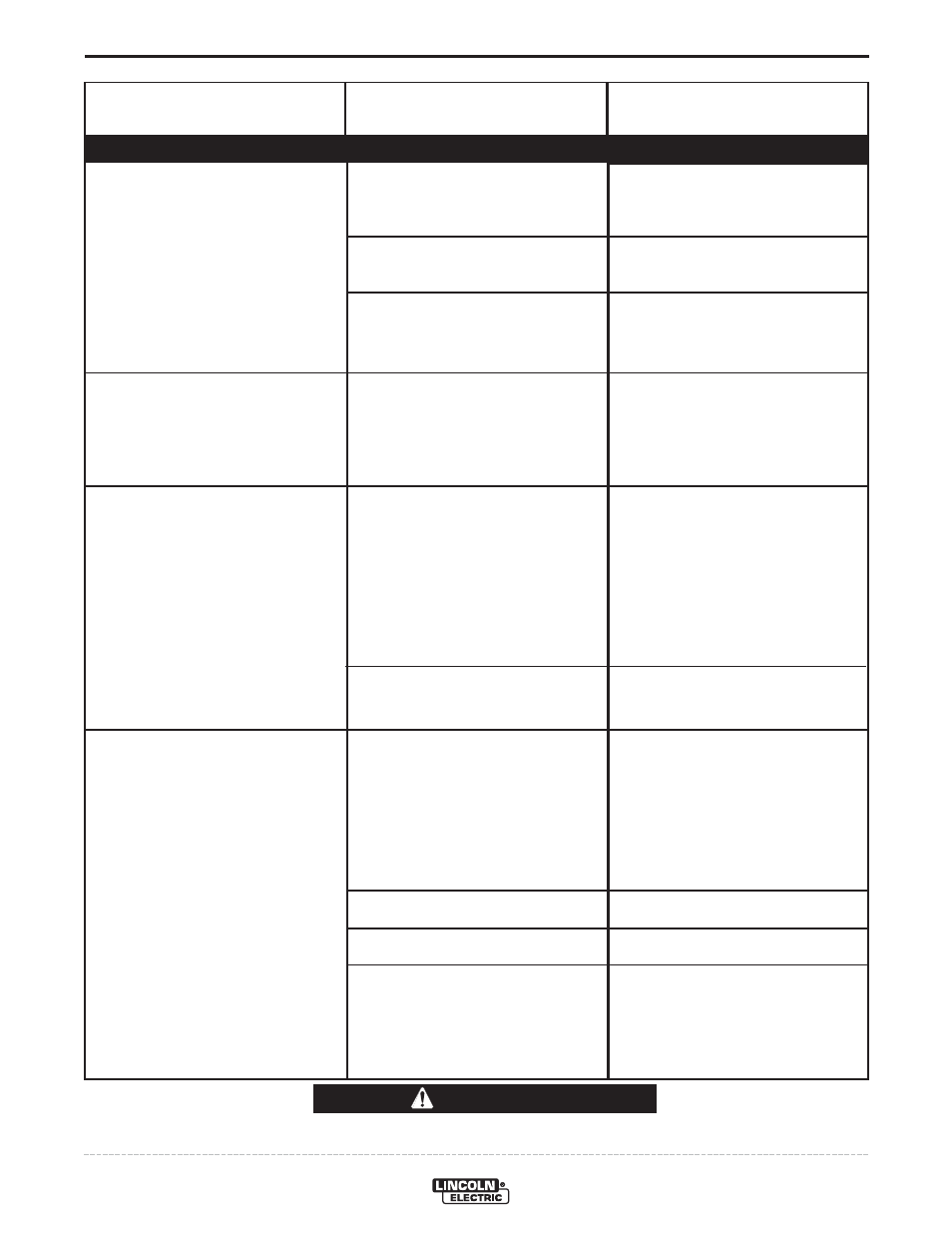
TROUBLESHOOTING
E-6
POWER WAVE
®
STT
®
MODULE (CE)
Observe all Safety Guidelines detailed throughout this manual
If for any reason you do not understand the test procedures or are unable to perform the tests/repairs safely, contact your
Local Lincoln Authorized Field Service Facility for technical troubleshooting assistance before you proceed.
CAUTION
PROBLEMS
(SYMPTOMS)
POSSIBLE
CAUSE
RECOMMENDED
COURSE OF ACTION
Input fuses keep blowing
Machine will not power up (no lights
on power source, STT
®
Module or
Wire Feeder).
No Status Light on STT
®
Module
Machine won’t weld, when attached
to STT
®
Module.
1. Improperly sized input fuses.
2. Improper Weld Procedure requir-
ing output levels in excess of
machine rating.
3. Major physical or electrical dam-
age is evident in the power source
when the sheet metal covers are
removed.
1. No Input Power.
1. 40VDC input not present at STT
®
Module.
2. Malfunctioning Status LED.
1. STT
®
Status Error.
2. STT
®
Thermal Error.
3. 40VDC input not present at STT
®
Module.
4. Internal open circuit
1. Make sure fuses are properly
sized. See installation section of
this manual for recommended
sizes.
2. Reduce output current, duty cycle,
or both.
3. Contact your local authorized
Lincoln Electric Field Service
facility for technical assistance.
1. Make sure input supply discon-
nect has been turned ON. Check
input fuses. Make certain that the
Power Switch on the power
source is in the “ON” position.
1 Check ArcLink
®
cable. Verify
40VDC per wiring diagram.
• If wire feeder is functional and
connected through the STT
®
Module, suspect connection
issue in STT
®
Module. Verify
condition of LED’s on STT
®
Switch PCB (viewable through
rear and left side louvers.
2. Verify status LED is properly
installed and has not disengaged
from the lens.
1. Make certain the polarity of the
STT
®
Module is correct per the
connection diagram (Positive to
STT Input).
• If polarity is correct, verify condi-
tion of LED’s on STT
®
Switch
PCB (viewable through rear and
left side louvers.
2. See “Thermal error indiction...”
section.
3. See “No Status Light on STT
®
…”
section.
4. Check for loose or broken connec-
tion in STT
®
Module weld circuit.
BASIC MACHINE PROBLEMS