Installation, A-5 remote sense lead connections – Lincoln Electric IM10057 POWER WAVE STT MODULE (CE) User Manual
Page 14
A-5
INSTALLATION
POWER WAVE
®
STT
®
MODULE (CE)
A-5
REMOTE SENSE LEAD CONNECTIONS
Voltage Sensing Overview
The STT
®
welding process requires the use of remote
voltage sense leads to more accurately monitor the
conditions of the arc. These leads originate in the
power source, and are connected and configured
external to the STT
®
Module. Consult the power
source instruction manual for detailed information.
Note:
Other processes run through the STT
®
Module do not
necessarily require sense leads, but will benefit from
their use. Consult the power source instruction manu-
al for recommendations.
General Voltage Sensing Considerations for
Multiple Arc Systems
Special care must be taken when more than one arc
is welding simultaneously on a single part. The place-
ment and configuration of remote work voltage sense
leads is critical to the proper operation of multiple arc
STT
®
applications.
RECOMMENDATIONS:
• Position the sense leads out of the path of the
weld current. Especially any current paths com-
mon to adjacent arcs. Current from adjacent arcs
can induce voltage into each others current paths
that can be misinterpreted by the power sources,
and result in arc interference.
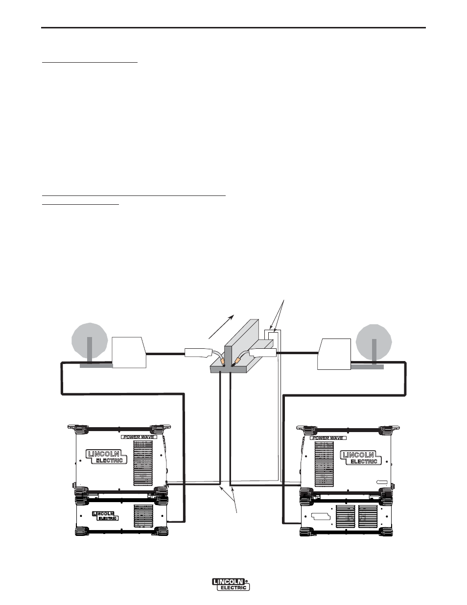
• For longitudinal applications, connect all work
leads at one end of the weldment, and all of the
work voltage sense leads at the opposite end of
the weldment. Perform welding in the direction
away from the work leads and toward the sense
leads. (See Figure A.4)
DIRECTION
OF TRAVEL
CONNECT ALL
WORK LEADS AT
THE BEGINNING
OF THE WELD.
CONNECT ALL SENSE
LEADS AT THE END
OF THE WELD.
FIGURE A.4