Troubleshooting, Caution, Preparation – Lincoln Electric IM10057 POWER WAVE STT MODULE (CE) User Manual
Page 22: Test procedure, Module functional test
E-2
TROUBLESHOOTING
E-2
POWER WAVE
®
STT
®
MODULE (CE)
Observe all Safety Guidelines detailed throughout this manual
If for any reason you do not understand the test procedures or are unable to perform the tests/repairs safely, contact your
Local Lincoln Authorized Field Service Facility for technical troubleshooting assistance before you proceed.
CAUTION
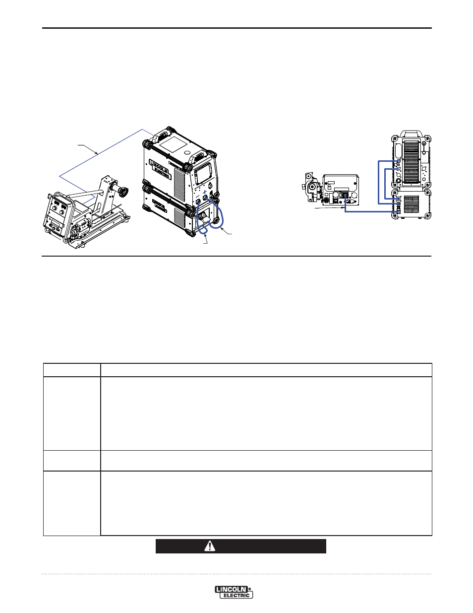
PREPARATION
• Connect the STT
®
module to a Power Wave S350 or other compatible machine.
(This test assumes the host power source has been calibrated.)
• Verify the latest software is loaded in the Power Wave.
• Short the Work (-) to the Electrode (STT
®
Output).
(Total Cable Length
≤ 10ft.)
TEST PROCEDURE
• Enable test modes on the UI of the Wire Feeder.
See Wire Feeder instruction manual (set-up menu selection P.99).
• Select test mode 208 (STT
®
Test Mode).
If mode 208 is not available with the test modes enabled, the Power Source software must be updated.
• Enable the output.
Pulling the trigger, or turn the trim knob clockwise.
• Read Voltage feedback displayed on the Wire Feeder Display.
Voltage
< 2V
5 - 10V
> 40V
Indication / Possible Cause
STT
®
Switch Shorted:
• Faulty or disconnected Differential I/O control signal (grey cable located at rear of module).
Verify cable connections (including those internal to the STT
®
Switch and host power source).
• STT
®
Input tied to negative weld output (Reverse Polarity, typically accompanied by Error 99).
Verify STT
®
Switch is properly connected.
• STT
®
Switch Shorted (typically accompanied by Error 99).
Disconnect and perform STT
®
Switch PCB Test.
Normal Operation
STT
®
Switch Open:
• Loose or open connection.
Verify weld cable connections (both internal and external to the module – including quick
connections).
• STT
®
Switch not closing (may be accompanied by Error 99).
Verify status of the STT
®
Switch board via the “on board” diagnostic LEDʼs.
STT OUTPUT TO
STT INPUT TO
POSITIVE STUD
NEGATIVE STUD
K1543-XX
K1543-XX
TO STT MODULE
STT
®
MODULE FUNCTIONAL TEST