Installation – Lincoln Electric IM10057 POWER WAVE STT MODULE (CE) User Manual
Page 13
A-4
INSTALLATION
POWER WAVE
®
STT
®
MODULE (CE)
A-4
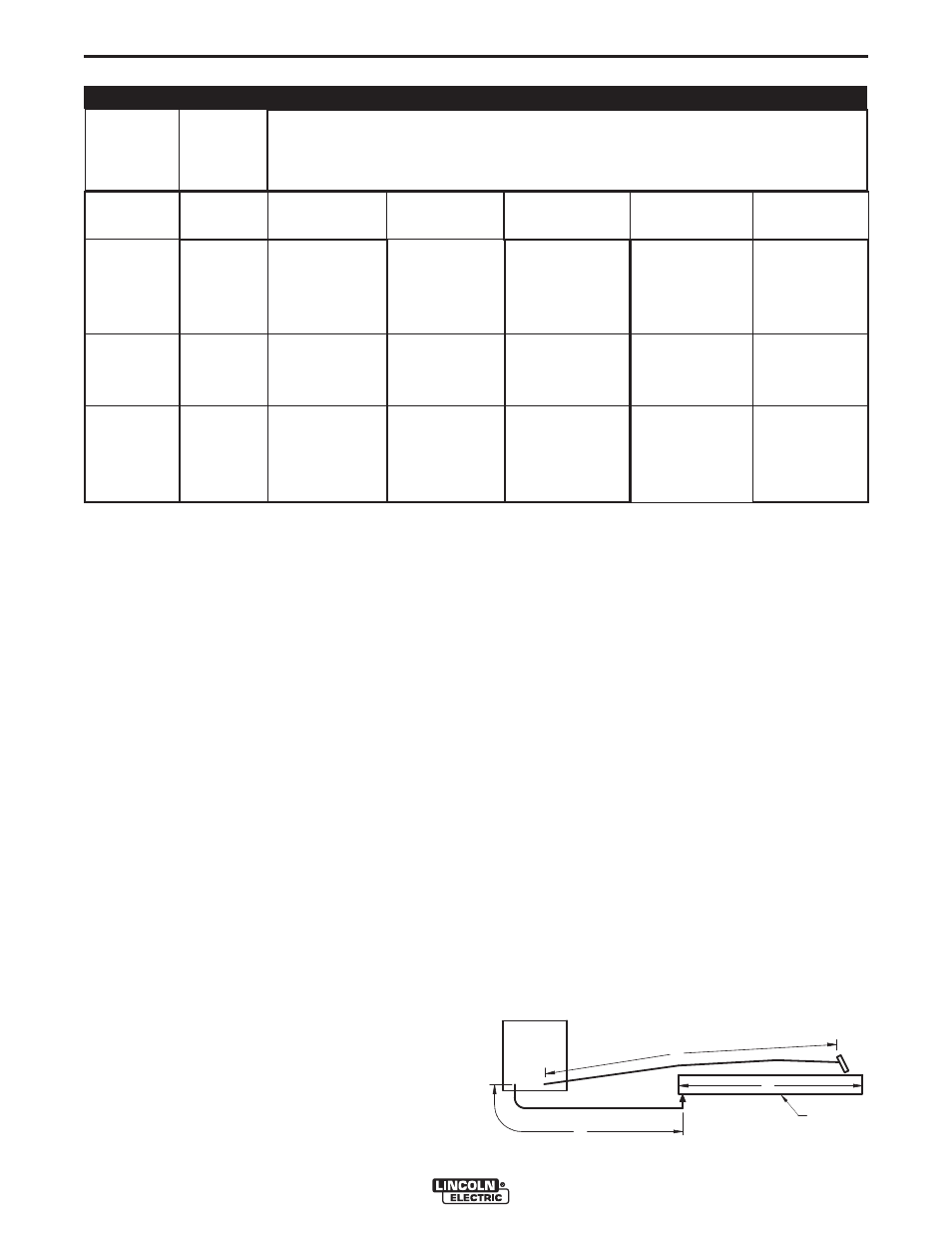
CABLE INDUCTANCE AND ITS EFFECTS
ON WELDING
Excessive cable inductance will cause the welding
performance to degrade. There are several factors
that contribute to the overall inductance of the cabling
system including cable size, and loop area. The loop
area is defined by the separation distance between
the electrode and work cables, and the overall welding
loop length. The welding loop length is defined as the
total of length of the electrode cable (A) + work cable
(B) + work path (C) (see Figure A.3 below). To mini-
mize inductance always use the appropriate size
cables, and whenever possible, run the electrode and
work cables in close proximity to one another to mini-
mize the loop area. Since the most significant factor in
cable inductance is the welding loop length, avoid
excessive lengths and do not coil excess cable. For
long work piece lengths, a sliding ground should be
considered to keep the total welding loop length as
short as possible.
GENERAL GUIDELINES
• Select the appropriate size cables per the “Output
Cable Guidelines” (See Table A.1. Excessive
voltage drops caused by undersized welding
cables and poor connections often result in unsat-
isfactory welding performance. Always use the
largest welding cables (electrode and work) that
are practical, and be sure all connections are clean
and tight.
Note: Excessive heat in the weld circuit indicates
undersized cables and/or bad connections.
• Route all cables directly to the work and wire feed-
er, avoid excessive lengths and do not coil excess
cable. Route the electrode and work cables in
close proximity to one another to minimize the loop
area and therefore the inductance of the weld cir-
cuit.
• Always weld in a direction away from the work
(ground) connection.
See Table A.1 for copper cable sizes recommended
for different currents and duty cycles. Lengths stipulat-
ed are the distance from the welder to work and back
to the welder again. Cable sizes are increased for
greater lengths primarily for the purpose of minimizing
cable drop.
OUTPUT CABLE GUIDELINES
TABLE A.1
CABLE SIZES FOR COMBINED LENGTHS OF ELECTRODE AND WORK CABLES
(RUBBER COVERED COPPER - RATED 75°C)**
Percent
Duty
Cycle
60
100
20
40 & 30
30
40
60
100
60
100
60
60
100
60
2
2
4 or 5
3
3
2
1
1
1
2/0
1/0
2/0
3/0
2/0
2
2
3
3
3
2
1
1
1
2/0
1/0
2/0
3/0
2/0
2
2
2
2
2
1
1
1
1
2/0
2/0
2/0
3/0
3/0
1
1
1
1
1
1
1
1
1/0
2/0
2/0
3/0
3/0
3/0
1/0
1/0
1/0
1/0
1/0
1/0
1/0
1/0
2/0
3/0
3/0
4/0
4/0
4/0
200
200
225
225
250
250
250
250
300
325
350
400
400
500
Amperes
0 to 50 Ft.
50 to 100 Ft. 100 to 150 Ft. 150 to 200 Ft. 200 to 250 Ft.
** Tabled values are for operation at ambient temperatures of 40°C and below. Applications above 40°C may require cables larger than
recommended, or cables rated higher than 75°C.
B
A
C
POWER
WAVE
FIGURE A.3
WORK