Operation – Lincoln Electric IM10057 POWER WAVE STT MODULE (CE) User Manual
Page 18
B-2
OPERATION
B-2
Although the STT
®
Module can be configured to support
negative electrode polarity processes, such as
Innershield, the STT
®
process must be configured to use
positive electrode polarity.
EQUIPMENT LIMITATIONS
The POWER WAVE
®
STT
®
MODULE (CE) is intended
for use with compatible medium range “S” – series
POWER WAVE
®
power sources such as the S350.
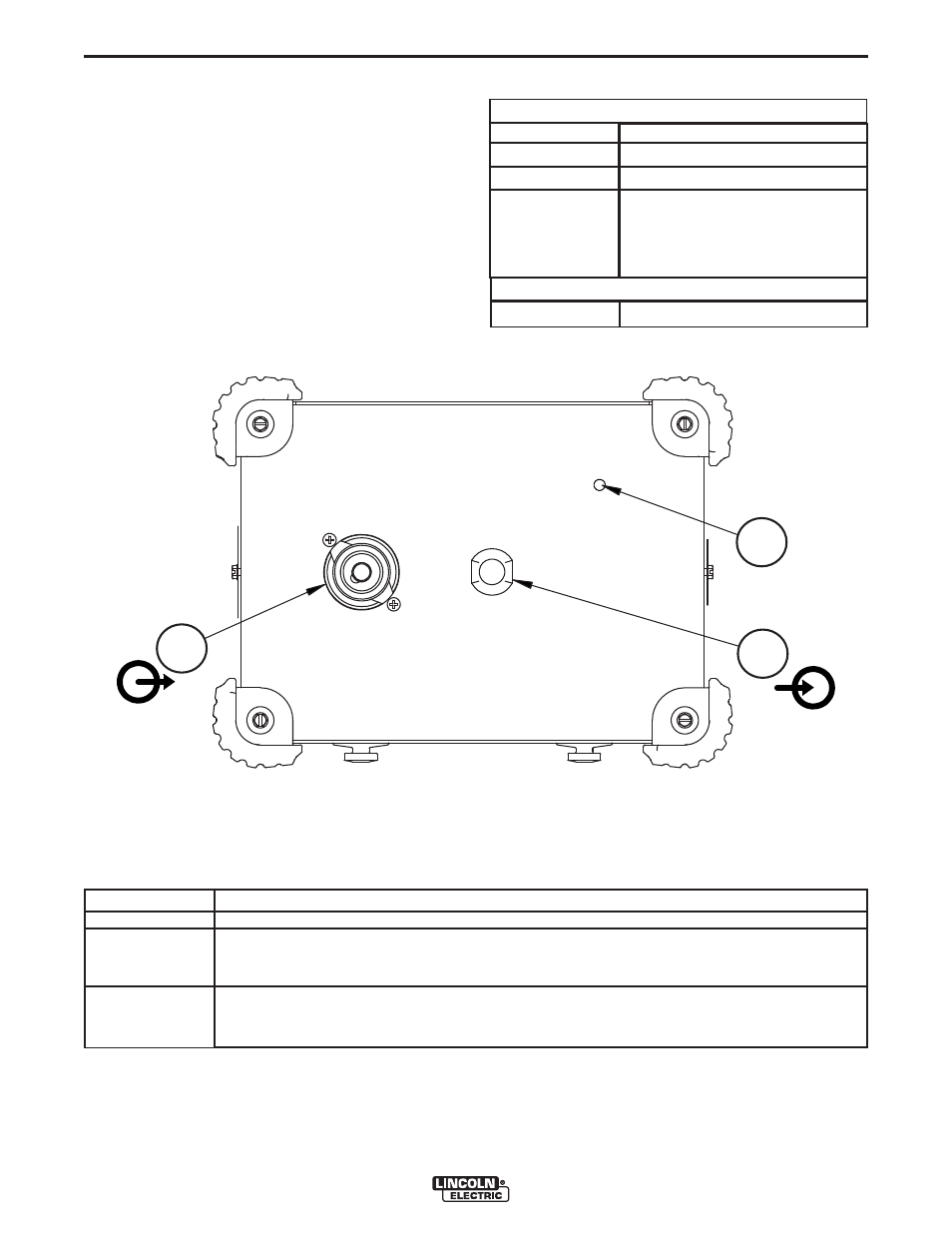
CASE FRONT DESCRIPTIONS
1. Status LED – Provides ArcLink
®
status of Power Wave STT Module.
Note: During normal power-up, the LED will flash green up to 60 seconds as the equipment performs self tests.
2. STT INPUT – Connects directly to the Positive output of the power source.
3. STT OUTPUT – Connects directly to the wire feeder, torch or electrode.
STT
®
MODULE (CE) CASE FRONT
COMMON EQUIPMENT PACKAGES
POWER WAVE
®
STT
®
MODULE (CE)
K2921-1
K2823-2
K14072-1
K1543-xx
LED condition
Steady green.
Blinking green.
Alternating green
and red
.
K2536
STT
®
Module (CE)
Power Wave
®
S350 (CE)
LF-45
ArcLink
®
Cable (5 pin) – con-
nects wire feeder to power
source.
Definition
System okay. The power source and wire feeder are communicating normally.
Occurs during a reset and indicates the power source is identifying each component in the
system. This is normal for the first 60 seconds after power-up, or if the system configuration
is changed during operation.
Non-recoverable system fault. If the power source or wire feeder status LED is flashing any
combination of red and green, errors are present in the system. Read the error code before
the machine is turned off.
PF-25M
BASIC PACKAGE (CE)
OPTIONAL WIRE FEEDERS
3
2
1