Installation, Caution, Caution warning – Lincoln Electric IM10057 POWER WAVE STT MODULE (CE) User Manual
Page 12: Connection between power source and stt, Module (arclink, And differential i/o pigtails), Electrode and work connections
A-3
INSTALLATION
POWER WAVE
®
STT
®
MODULE (CE)
A-3
Regarding cable placement, best results will be
obtained when control cables are routed separate
from the weld cables. This minimizes the possibili-
ty of interference between the high currents flow-
ing through the weld cables, and the low level sig-
nals in the control cables. These recommenda-
tions apply to all communication cables including
ArcLink
®
connections.
------------------------------------------------------------------------
CONNECTION BETWEEN POWER
SOURCE AND STT
®
MODULE (ARCLINK
®
AND DIFFERENTIAL I/O PIGTAILS)
The pigtail connections on the STT
®
Module include all
signal and power lines required for proper operation.
With the STT
®
Module securely fastened to the power
source, connect the pigtails to their respective recep-
tacles on the back of the power source per the con-
nection diagram located in the “Installation Section”.
Special Instructions:
K2921-1
A special ArcLink
®
and Differential I/O receptacle kit
is provided with the STT
®
Module for installation into
the host power source. Follow the instructions pro-
vided with the kit. (reference instruction sheet
M22499).
ELECTRODE AND WORK CONNECTIONS
Connect the electrode and work cables per the con-
nection diagrams included in this document. Size and
route the cables per the following:
• Positive Electrode Polarity: Most welding appli-
cations run with the electrode being positive (+).
For those applications, connect the electrode cable
between the wire drive feed plate and the output
stud on the STT Module. Connect a work lead from
the negative (-) power source output stud to the
work piece per the Connection Diagram.
(See Figure A.5)
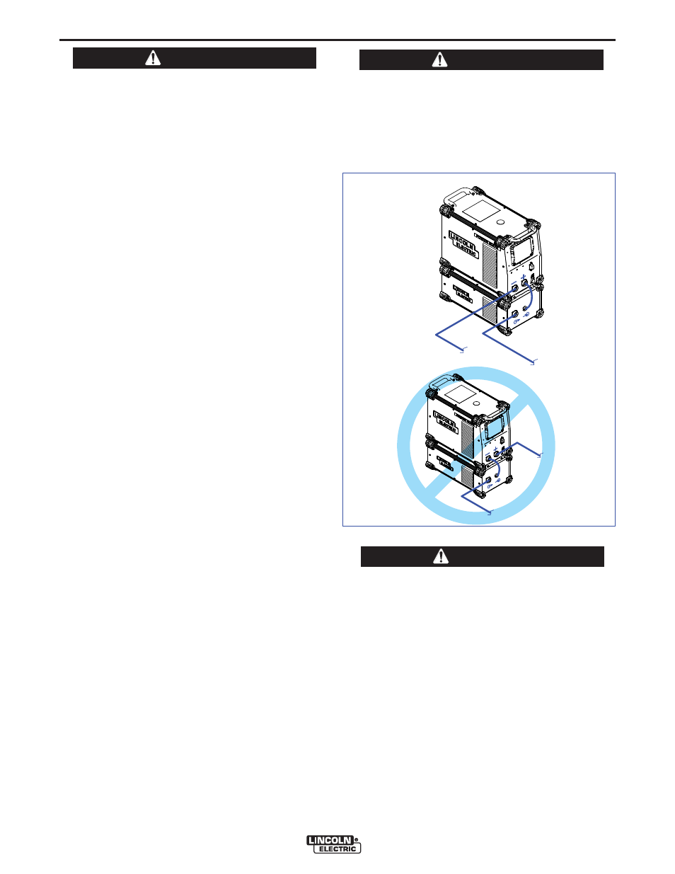
• Negative Electrode Polarity: The STT process
CANNOT be run using negative electrode polarity.
However, for processes other than STT requiring
negative polarity, such as some Innershield appli-
cations, the electrode and work connections
should be reversed at the load, NOT at the input to
the STT Module. Connect the electrode cable to
the negative (-) stud of the power source, and work
cable to the output stud of the STT Module per the
Negative Polarity Connection Diagram.
(See Figure A.2)
Negative electrode polarity operation may require
reconfiguration of the power source voltage sense
leads. See the Remote Sense Lead section in the
power source instruction manual for further
details.
------------------------------------------------------------------------
For additional Safety information regarding the elec-
trode and work cable set-up, See the standard
“SAFETY INFORMATION” located in the front of the
Instruction Manuals.
Never reverse the polarity at the input of the STT
Module (DO NOT connect the negative stud of the
power source to input stud of the STT Module).
This may result in damage to the STT Module!
------------------------------------------------------------------------
CAUTION
CAUTION
WARNING
TO ELECTRODE
(FEEDER)
TO WORK
TO WORK
TO ELECTRODE
(FEEDER)
NEGATIVE POLARITY
CONNECTION
(
NOT TO BE USED FOR
STT PROCESS)
FIGURE A.2