1 at power mode, 2 atx power mode, Figure 5-13: at/atx switch location – IEI Integration AFL2-W19A-H61 v1.11 User Manual
Page 78: Figure 5-13), Figure 5-13 )
AFL2-W19A/AB-H61
P a g e 59
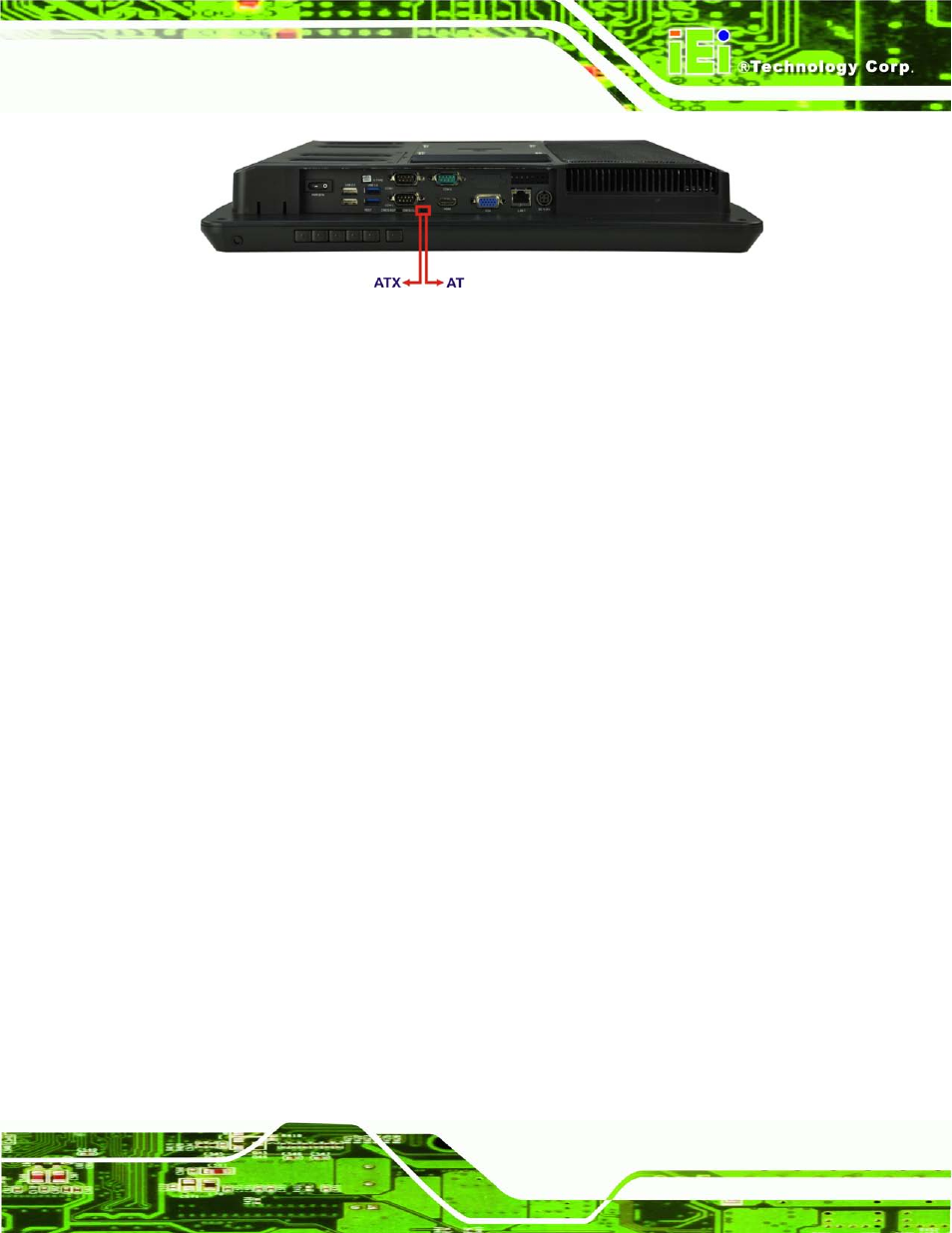
Figure 5-13: AT/ATX Switch Location
S te p 2:
Adjust the AT/ATX switch.
5.8.1 AT P o we r Mo d e
With the AT mode selected, the power is controlled by a central power unit rather than a
power switch. The AFL2-W19A/AB-H61 panel PC turns on automatically when the power
is connected. The AT mode benefits a production line to control multiple panel PCs from a
central management center and other applications including:
ATM
Self-service kiosk
Plant environment monitoring system
Factory automation platform
Manufacturing shop flow
5.8.2 ATX P o we r Mo d e
With the ATX mode selected, the AFL2-W19A/AB-H61 panel PC goes in a standby mode
when it is turned off. The panel PC can be easily turned on via network or a power switch
in standby mode. Remote power control is perfect for advertising applications since the
broadcasting time for each panel PC can be set individually and controlled remotely. Other
possible application includes
Security surveillance
Point-of-Sale (POS)
Advertising terminal