7 usb cable (dual port without bracket) (optional) – IEI Integration WAFER-945GSE2 v1.03 User Manual
Page 93
WAFER-945GSE2 User Manual
Page 76
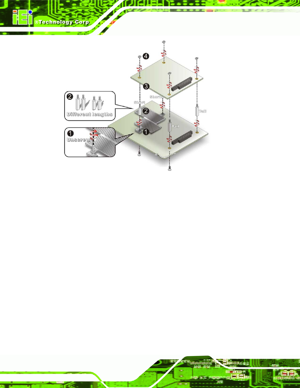
Figure 5-14: WAFER-945GSE2 PC/104 module installation
Step 1:
Remove retention nuts. Remove the two nuts securing the heatsink and two
nuts securing the WAFER-945GSE2 to the chassis.
Step 2:
Attach intermediate poles. Insert the two short plastic intermediate poles into
the bolts securing the heatsink. Insert the two tall plastic intermediate poles.
Step 3:
Align the PC/104 connector. Align the PC/104 module connector with the
corresponding connector on the WAFER-945GSE2 (connector CN2). Gently
push the module down to ensure the connectors are properly connected.
Step 4:
Replace the retention nuts. Screw the four retention nuts onto the
intermediate poles to secure the PC/104 module.
5.6.7 USB Cable (Dual Port without Bracket) (Optional)
The WAFER-945GSE2 is shipped with a dual port USB 2.0 cable. To connect the USB
cable connector, please follow the steps below.
Step 5:
Locate the connectors. The locations of the USB connectors are shown in