4 jumper settings, 1 at/atx power select jumper settings, Umper – IEI Integration WAFER-945GSE2 v1.03 User Manual
Page 79: Ettings, Figure 5-2: jumper locations, Table 5-1: jumpers
WAFER-945GSE2 User Manual
Page 62
5.4 Jumper Settings
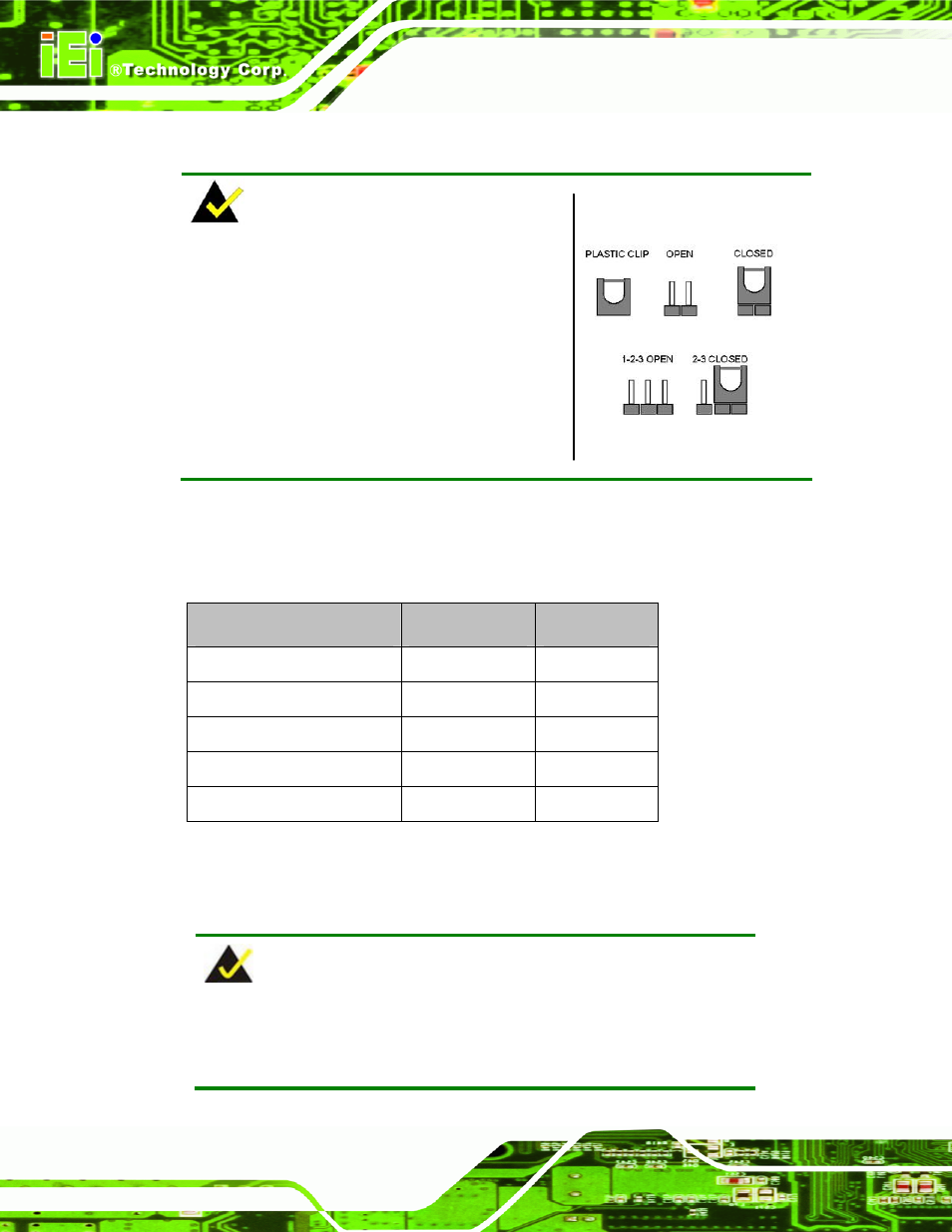
NOTE:
A jumper is a metal bridge used to close an
electrical circuit. It consists of two or three metal
pins and a small metal clip (often protected by a
plastic cover) that slides over the pins to connect
them. To CLOSE/SHORT a jumper means
connecting the pins of the jumper with the plastic
clip and to OPEN a jumper means removing the
plastic clip from a jumper.
Figure 5-2: Jumper Locations
Before the WAFER-945GSE2 is installed in the system, the jumpers must be set in
accordance with the desired configuration. The jumpers on the WAFER-945GSE2 are
listed in
8
Table 5-1.
Description
Label
Type
AT/ATX power mode setting
ATXCTL1
3-pin header
CF card setting
JCF1
2-pin header
Clear CMOS setup
J_CMOS1
3-pin header
COM2 mode setting
JP1
8-pin header
LVDS1 voltage select
J_VLVDS1
3-pin header
Table 5-1: Jumpers
5.4.1 AT/ATX Power Select Jumper Settings
NOTE:
The AT Power Select Jumper is the same as the ATX Enable
connector.