4 4-com port adapter board connection (optional), Figure 4-12: dual rs-232 cable installation – IEI Integration WAFER-945GSE v2.01 User Manual
Page 69
WAFER-945GSE 3.5" Motherboard
Page 54
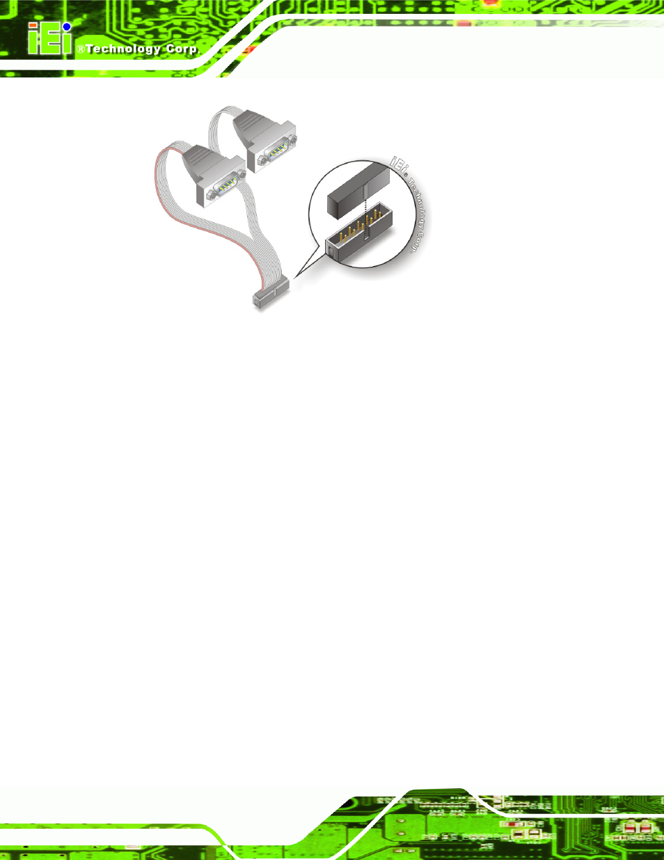
Figure 4-12: Dual RS-232 Cable Installation
Step 3:
Secure the connectors. Both single RS-232 connectors have two retention
screws that must be secured to a chassis or bracket.
Step 4:
Connect the serial device. Once the single RS-232 connectors are connected
to a chassis or bracket, a serial communications device can be connected to the
system.
4.6.4 4-COM Port Adapter Board Connection (Optional)
An optional, separately purchased 4-COM port adapter board may be shipped with the
WAFER-945GSE. To install the 4-COM Port Adapter Board, please follow the steps
below.
Step 1:
Locate the COM connector. The locations of the COM port connectors are
shown in Chapter 3.
Step 2:
Insert the cable connector. Align the cable connector with the onboard
connector. Make sure the pin 1on the cable connector is properly aligned with
pin 1 on the board connector (Figure 4-13).
Step 3:
Connect the adapter board to the cable. The adapter board with the four COM
ports must then be attached to the cable. Make sure the cable connector is