IEI Integration WAFER-945GSE v2.01 User Manual
Wafer-945gse, User manual, Model
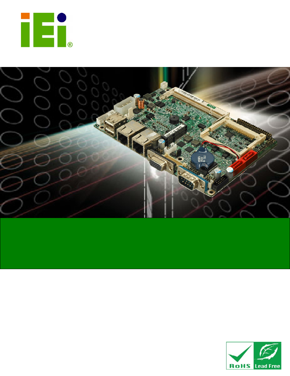
Table of contents
Document Outline
- 1 Introduction
- 2 Packing List
- 3 Connectors
- 3.1 Peripheral Interface Connectors
- 3.2 Internal Peripheral Connectors
- 3.2.1 ATX Power Connector
- 3.2.2 ATX Power Supply Enable Connector
- 3.2.3 Audio Connector (10-pin)
- 3.2.4 Backlight Inverter Connector
- 3.2.5 CompactFlash® Socket
- 3.2.6 Digital Input/Output (DIO) Connector
- 3.2.7 Fan Connector (+12V, 3-pin)
- 3.2.8 Keyboard/Mouse Connector
- 3.2.9 LED Connector
- 3.2.10 LVDS LCD Connector
- 3.2.11 PCIe Mini Card Slot
- 3.2.12 Power Button Connector
- 3.2.13 Reset Button Connector
- 3.2.14 SATA Drive Connectors
- 3.2.15 Serial Port Connectors, RS-232
- 3.2.16 Serial Port Connector, RS-232/422/485
- 3.2.17 SPI Flash Connector
- 3.2.18 USB Connectors (Internal)
- 3.3 External Peripheral Interface Connector Panel
- 4 Installation
- 4.1 Anti-static Precautions
- 4.2 Installation Considerations
- 4.3 SO-DIMM and CF Card Installation
- 4.4 Jumper Settings
- 4.5 Chassis Installation
- 4.6 Internal Peripheral Device Connections
- 4.6.1 SATA Drive Connection
- 4.6.2 Serial Port Connector Cable (Four Ports) Cable Connection
- 4.6.3 Dual RS-232 Cable Connection (w/o bracket) (Optional)
- 4.6.4 4-COM Port Adapter Board Connection (Optional)
- 4.6.5 Keyboard/Mouse Y-cable Connector
- 4.6.6 Audio Kit Installation
- 4.6.7 USB Cable (Dual Port without Bracket) (Optional)
- 4.7 External Peripheral Interface Connection
- 4.8 Heat Sink Enclosure
- 5 BIOS
- 6 Software Drivers
- A BIOS Options
- B One Key Recovery
- C Terminology
- D Digital I/O Interface
- E Watchdog Timer
- F Hazardous Materials Disclosure