1 ethernet connectors, Figure 3-21: rj-45 ethernet connector, Table 3-21: lan pinouts – IEI Integration WAFER-945GSE v2.01 User Manual
Page 50: Table 3-22: rj-45 ethernet connector leds
WAFER-945GSE 3.5" Motherboard
Page 35
3.3.1 Ethernet Connectors
CN Label:
LAN1 and LAN2
CN Type:
RJ-45 connector
CN Location:
CN Pinouts:
The WAFER-945GSE is equipped with two built-in RJ-45 Ethernet controllers. The
controllers can connect to the LAN through two RJ-45 LAN connectors. There are two
LEDs on the connector indicating the status of LAN. The pin assignments are listed in the
following table:
Pin
Description
Pin
Description
1
MDIA3-
2
MDIA3+
3
MDIA2-
4
MDIA1-
5
MDIA1+
6
MDIA2+
7
MDIA0-
8
MDIA0+
Table 3-21: LAN Pinouts
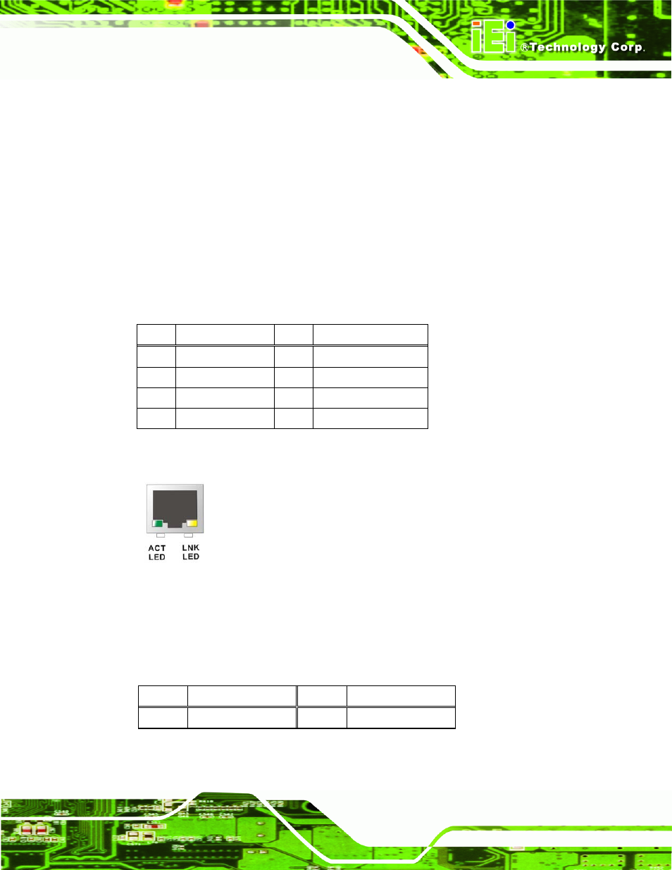
Figure 3-21: RJ-45 Ethernet Connector
The RJ-45 Ethernet connector has two status LEDs, one green and one yellow. The green
LED indicates activity on the port and the yellow LED indicates the port is linked. See
Status Description
Status Description
Green Activity
Yellow Linked
Table 3-22: RJ-45 Ethernet Connector LEDs