16 serial port connector, rs-232/422/485, Table 3-17: com3 to com6 connector pinouts – IEI Integration WAFER-945GSE v2.01 User Manual
Page 46
WAFER-945GSE 3.5" Motherboard
Page 31
Pin Description
Pin Description
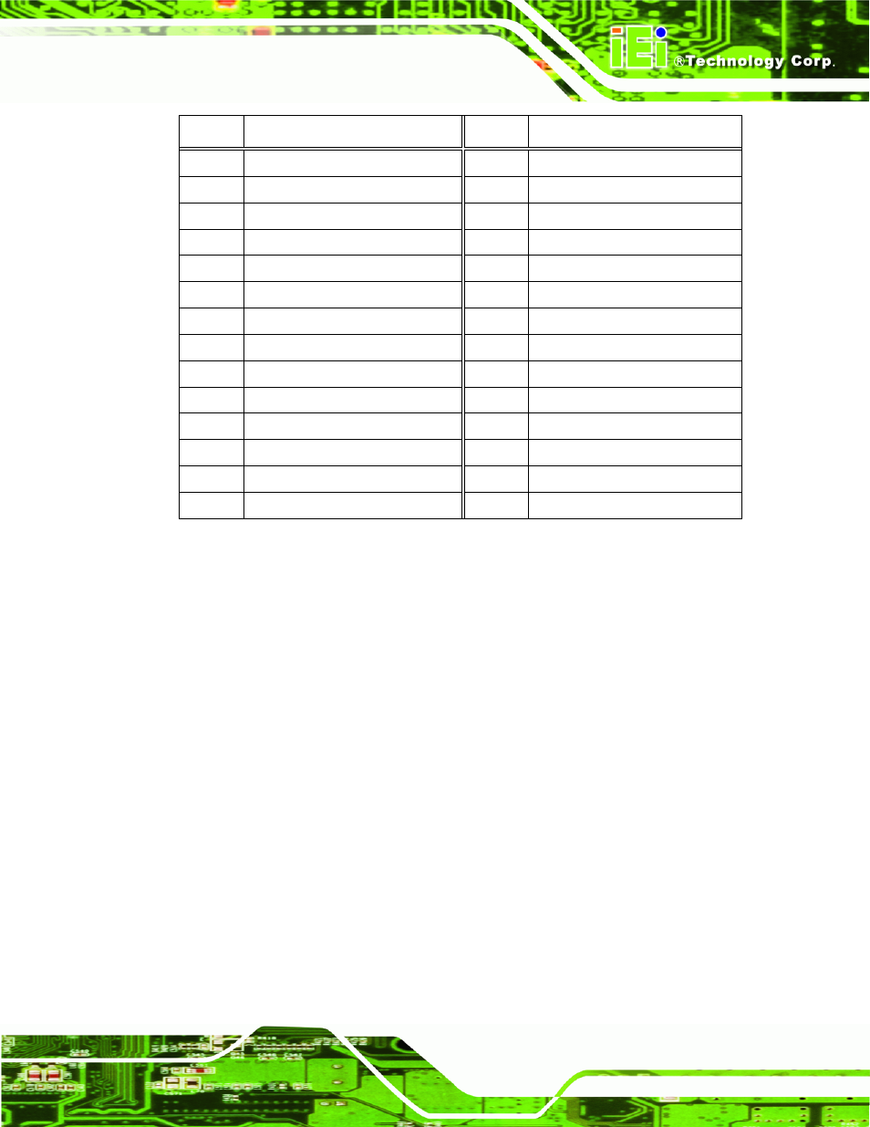
13
RECEIVE DATA (RXD4)
14
REQUEST TO SEND (RTS4)
15
TRANSMIT DATA (TXD4)
16
CLEAR TO SEND (CTS4)
17
DATA TERMINAL READY (DTR4)
18
RING INDICATOR (RI4)
19 GND
20 GND
21
DATA CARRIER DETECT (DCD5)
22
DATA SET READY (DSR5)
23
RECEIVE DATA (RXD5)
24
REQUEST TO SEND (RTS5)
25
TRANSMIT DATA (TXD5)
26
CLEAR TO SEND (CTS5)
27
DATA TERMINAL READY (DTR5)
28
RING INDICATOR (RI5)
29 GND
30 GND
31
DATA CARRIER DETECT (DCD6
32
DATA SET READY (DSR6)
33
RECEIVE DATA (RXD6)
34
REQUEST TO SEND (RTS6)
35
TRANSMIT DATA (TXD6
36
CLEAR TO SEND (CTS6)
37
DATA TERMINAL READY (DTR6
38
RING INDICATOR (RI6)
39 GND
40 GND
Table 3-17: COM3 to COM6 Connector Pinouts
3.2.16 Serial Port Connector, RS-232/422/485
CN Label:
COM2
CN Type:
14-pin header
CN Location:
CN Pinouts:
The 14-pin serial port connector connects to the COM2 serial communications channels.
COM2 is a multi function channel. In default mode COM2 is an RS-232 serial
communication channel but, with the COM2 function select jumper, can be configured as
either an RS-422 or RS-485 serial communications channel.