1 north bridge chipset configuration, Bios menu 19: north bridge chipset configuration – IEI Integration WAFER-945GSE v2.01 User Manual
Page 115
WAFER-945GSE 3.5" Motherboard
Page 100
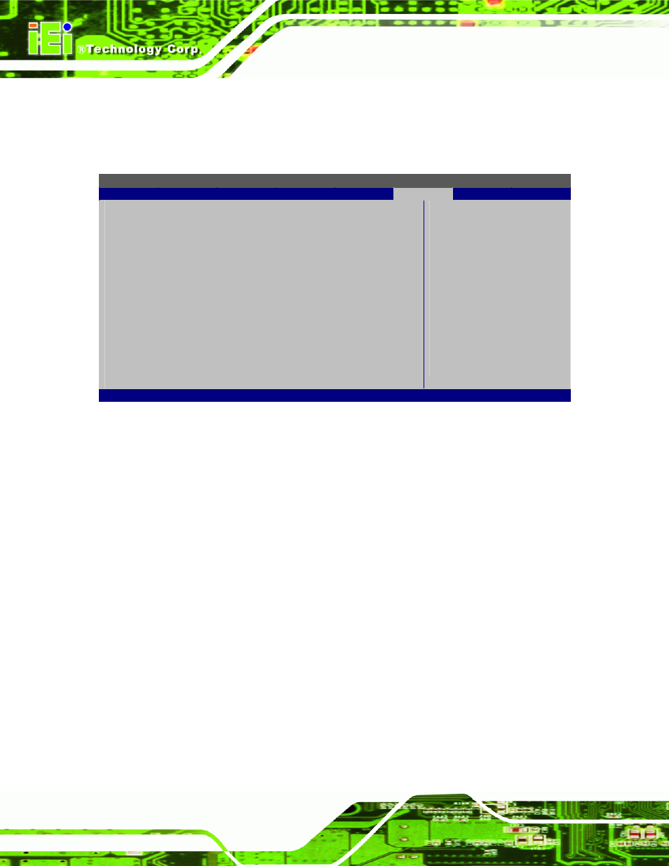
5.7.1 North Bridge Chipset Configuration
Use the North Bridge Chipset Configuration menu (BIOS Menu 19) to configure the
Northbridge chipset settings.
BIOS SETUP UTILITY
Chipset
North Bridge Chipset Configuration
⎯⎯⎯⎯⎯⎯⎯⎯⎯⎯⎯⎯⎯⎯⎯⎯⎯⎯⎯⎯⎯⎯⎯⎯⎯⎯⎯⎯⎯⎯⎯
Memory Hole
[Disabled]
Internal Graphics Mode Select
[Enabled, 8MB]
Video Function Configuration
⎯⎯⎯⎯⎯⎯⎯⎯⎯⎯⎯⎯⎯⎯⎯⎯⎯⎯⎯⎯⎯⎯⎯⎯⎯⎯⎯⎯⎯⎯⎯
DVMT Mode Select
[DVMT Mode]
DVMT/FIXED Memory
[Maximum DVMT]
Boot Display Device
[Auto]
LVDS1 Panel Type
[by H/W]
LVDS1 Current Jumper Setting
[8000x600 18b]
Options
Disabled
15MB-16MB
Select
Screen
↑ ↓ Select
Item
+ -
Change Option
F1 General
Help
F10
Save and Exit
ESC Exit
v02.61 ©Copyright 1985-2006, American Megatrends, Inc.
BIOS Menu 19: North Bridge Chipset Configuration
Memory Hole [Disabled]
The Memory Hole reserves the memory space between 15MB and 16MB for ISA
expansion cards that require a specified area of memory to work properly. If an older ISA
expansion card is used, please refer to the documentation that came with the card to see if
it is necessary to reserve the space.
Disabled D
EFAULT
Memory is not reserved for ISA expansion cards
15MB-16MB
Memory is reserved for ISA expansion cards
Internal Graphics Mode Select [Enabled, 8MB]
The Internal Graphic Mode Select option determines the amount of system memory that
can be used by the internal graphics device.
Disabled
Enabled, 1MB
1MB of memory used by internal graphics device