7 sata drive connection, Figure 5-9: lpt cable connection – IEI Integration PCISA-945GSE v1.01 User Manual
Page 99
PCISA-945GSE CPU Card
Page 81
Step 2:
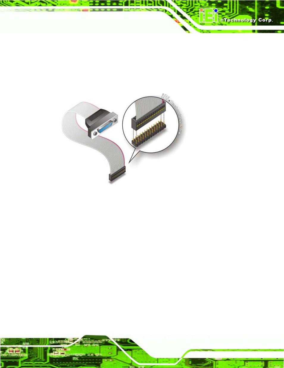
Align the connectors. Correctly align pin 1 on the cable connector with pin 1 on
the PCISA-945GSE LPT box-header connector. See Figure 5-9.
Step 3:
Insert the cable connectors
.
Once the cable connector is properly aligned with
the 26-pin box-header connector on the PCISA-945GSE, connect the cable
connector to the on-board connector. See Figure 5-9.
Figure 5-9: LPT Cable Connection
Step 4:
Attach the LPT connector to the chassis. To secure the LPT interface
connector to the chassis please refer to the installation instructions that came
with the chassis.
Step 5:
Connect LPT device. Once the LPT interface connector is connected to the
chassis, the LPT device can be connected to the LPT interface connector. See
5.8.7 SATA Drive Connection
The PCISA-945GSE is shipped with two SATA drive cables and one SATA drive power
cable. To connect the SATA drives to the connectors, please follow the steps below.
Step 6:
Locate the connectors. The locations of the SATA drive connectors are shown
in Chapter 3.