Figure 5-4: 5.1 channel audio kit – IEI Integration PCISA-945GSE v1.01 User Manual
Page 93
PCISA-945GSE CPU Card
Page 75
The optional 5.1 channel audio kit connects to the 10-pin audio connector on the
PCISA-945GSE. The audio kit consists of three audio jacks. One audio jack, Mic In,
connects to a microphone. The remaining two audio jacks, Line-In and Line-Out, connect
to two speakers. To install the audio kit, please refer to the steps below:
Step 4:
Connect the audio kit cable. The audio kit is shipped with a cable that
connects the audio kit to the PCISA-945GSE. Connect the cable to the
connector on the back of the audio kit. Make sure the pins are properly aligned
(i.e. pin 1 connects to pin 1).
Step 5:
Locate the audio connector. The location of the 10-pin audio connector is
shown in Chapter 3.
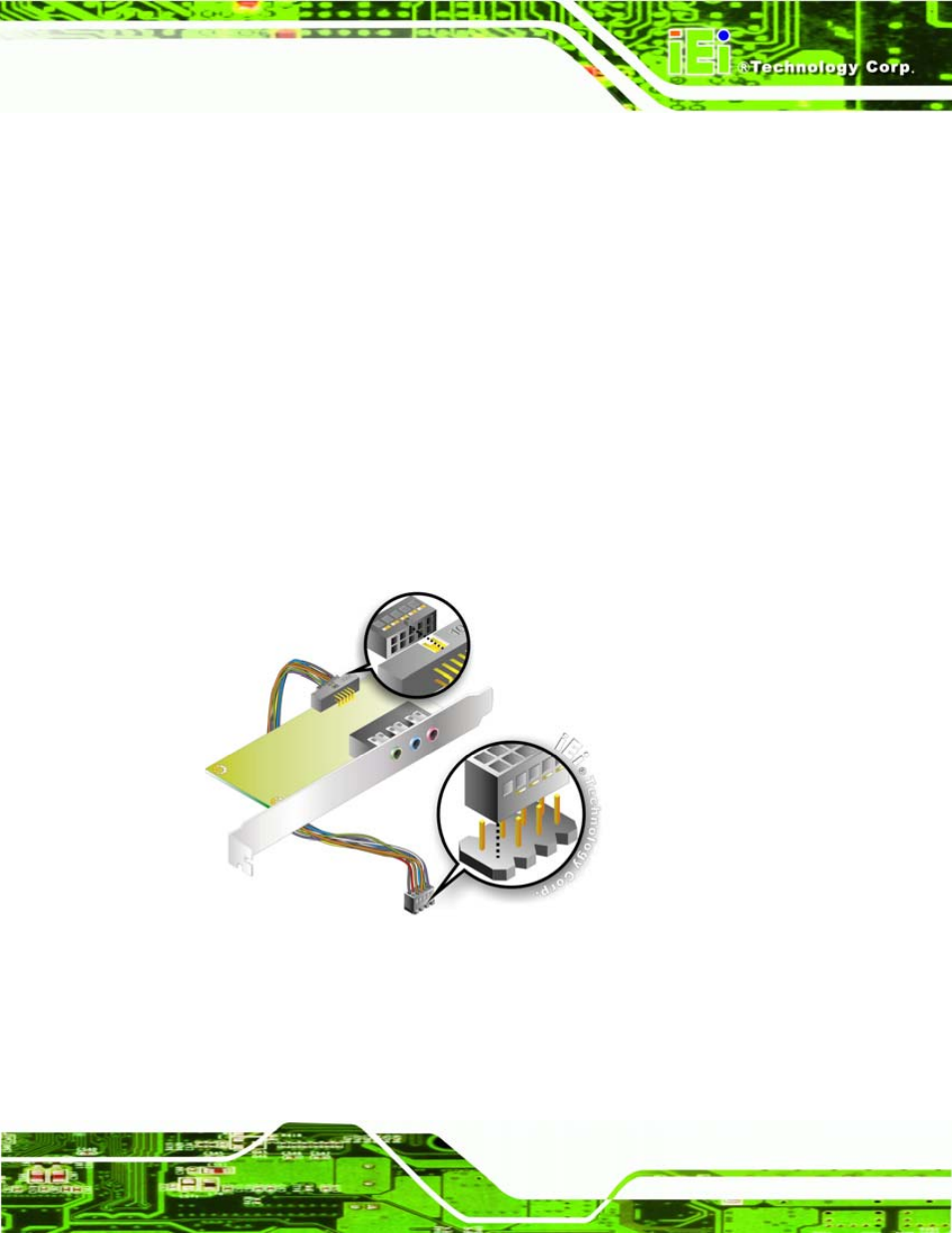
Step 6:
Align pin 1. Align pin 1 on the on-board connector with pin 1 on the audio kit
cable connector. Pin 1 on the audio kit cable connector is indicated with a white
dot. See Figure 5-4.
Figure 5-4: 5.1 Channel Audio Kit
Step 7:
Mount the audio kit onto the chassis. Once the audio kit is connected to the
PCISA-945GSE, secure the audio kit bracket to the system chassis.