3 external peripheral interface connector panel, 1 lan connectors, Xternal – IEI Integration PCISA-945GSE v1.10 User Manual
Page 59: Eripheral, Nterface, Onnector, Anel, Table 3-24: lan connector pinouts
PCISA-945GSE CPU Card
Page 41
3.3 External Peripheral Interface Connector Panel
7
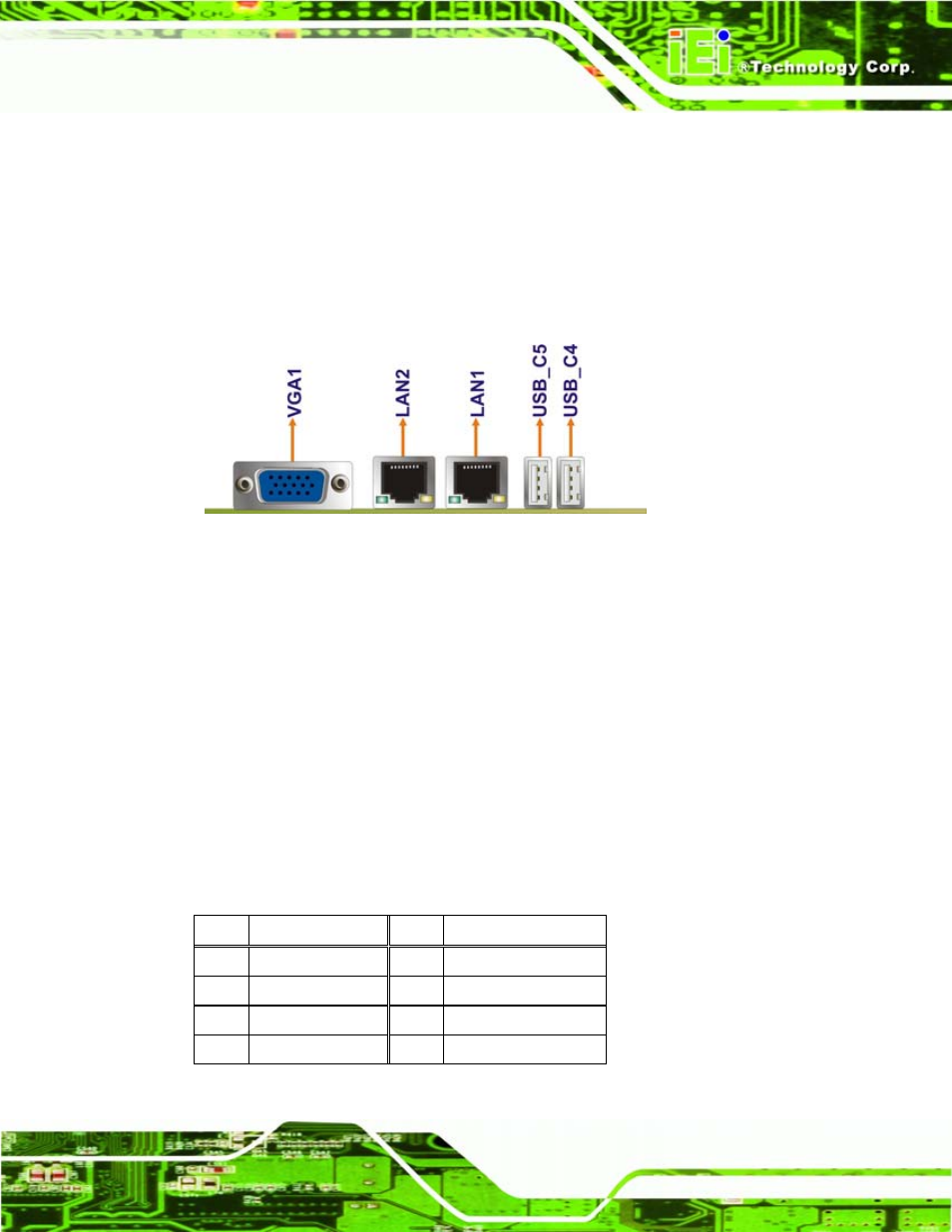
Figure 3-24 shows the PCISA-945GSE external peripheral interface connector (EPIC)
panel. The PCISA-945GSE EPIC panel consists of the following:
2 x RJ-45 LAN connectors
2 x USB connectors
1 x VGA connector
Figure 3-24: PCISA-945GSE External Peripheral Interface Connector
3.3.1 LAN Connectors
CN Label:
LAN1 and LAN2
CN Type:
RJ-45
CN Location:
See
7
Figure 3-24
CN Pinouts:
See
7
Table 3-24
The PCISA-945GSE is equipped with two built-in RJ-45 Ethernet controllers. The
controllers can connect to the LAN through two RJ-45 LAN connectors. There are two
LEDs on the connector indicating the status of LAN. The pin assignments are listed in the
following table:
PIN DESCRIPTION PIN DESCRIPTION
1 MDIA3-
5 MDIA1+
2 MDIA3+
6 MDIA2+
3 MDIA2-
7 MDIA0-
4 MDIA1-
8 MDIA0+
Table 3-24: LAN Connector Pinouts