4 installing optional hardware modules, 5 connecting power – Asante Technologies 3500 Series User Manual
Page 15
15
2.3.2 Removing a GBIC
Caution: GBIC 1000T modules run hot under normal operating conditions. When it has been removed from
the system, place it on a heat resistant surface and allow the module to cool before handling.
Note: Unnecessary removals/insertions of a GBIC module will lead to premature failure of the GBIC. The
rated duty cycle for a GBIC module is 100 to 500 removals/insertions.
Follow the steps below to remove a GBIC interface from a Gigabit Ethernet module:
1. Disconnect the cable from the GBIC module.
2.
Release the GBIC from the slot by simultaneously squeezing the locking tabs on both sides of the
GBIC.
3. Slide the GBIC out of the slot.
4. GBIC 1000SX and GBIC 1000LX modules: Install the rubber plugs in the GBIC optical bores, and
place the GBIC in protective packaging.
2.3.3 GBIC Care and Handling
Follow these GBIC maintenance guidelines:
•
GBICs are static-sensitive. To prevent ESD damage, follow your normal board and component
handling procedures. Wear an ESD wrist strap
•
GBIC 1000SX and GBIC 1000LX modules are very sensitive to dust and contaminants. When they
are not connected to a fiber-optic cable, install the rubber plugs in the optical bores
•
The ferrules of the optical connectors may pick up debris that can obstruct the optical bore. Use an
alcohol swab or equivalent to clean the ferrules of the optical connector
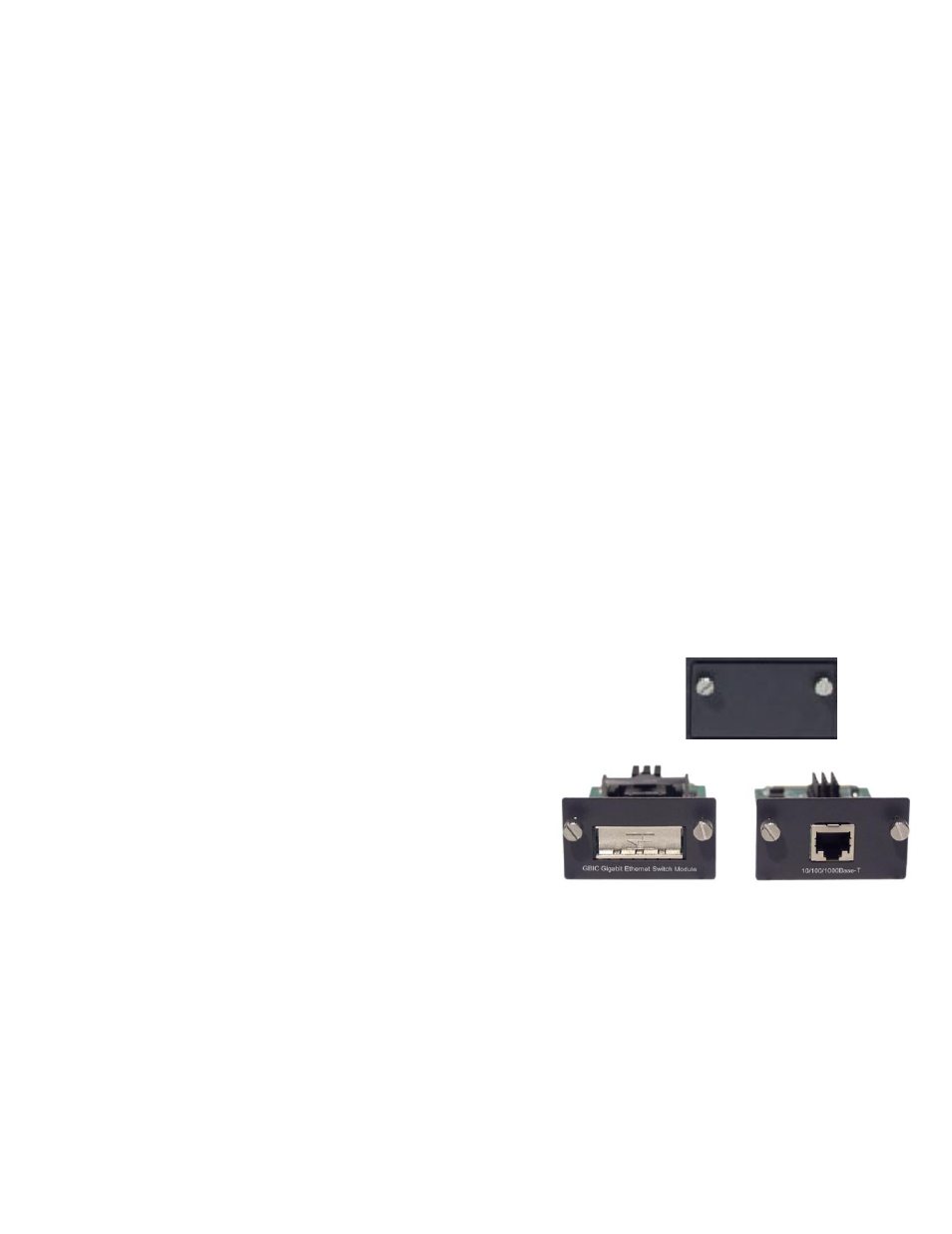
2.4 Installing Optional Hardware Modules
Follow the steps below to install your media modules (10/100/1000BaseT, 1000BaseX GBIC, 1000BaseSX
or 100BaseFX):
1. Using a flat-head screwdriver (not included), remove the slot cover plate
from the switch.
2. Touch a grounded, metal object to discharge any static electricity on your
body, and then remove the module from its protective packaging (being
careful not to touch any board components or connectors).
3. Slide the module firmly into the module slot until it has
clicked into place. The module’s faceplate should be
flush with the front panel of the switch.
4. Replace the screws to secure the module, being
careful not to over-tighten the screws.
5. Connect network cables to the module port.
6. Restore power to the switch if necessary, or reset the
switch.
2.5 Connecting Power
Use the following procedure to connect power to the switch:
Important: Carefully review the power requirements (Chapter 2.1.3) before connecting power to the switch.
1. Plug one end of the supplied power cord into the power connector on the back of the unit.
2. Plug the other end into a grounded AC outlet.
3. Turn on the switch’s power. The Power LED will begin its initialization process.
The front panel LEDs blink and the Power LED illuminates when it has initialized. The switch is ready for
connection to the network.