Horizontal mounting – Warner Electric CB Series Size 2 User Manual
Page 4
4
Warner Electric • 800-825-9050
P-1315 • 819-0448
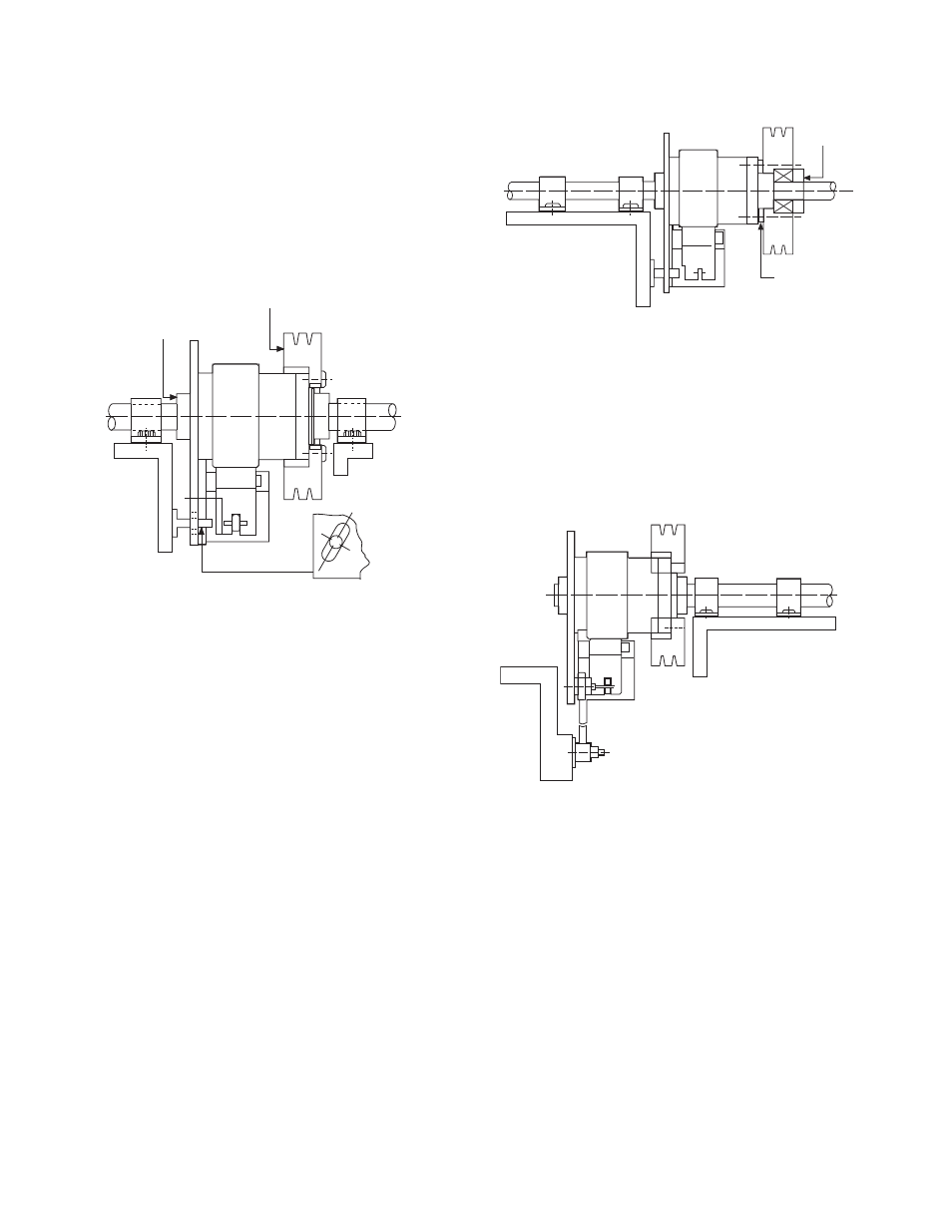
Figure 2 - Acceptable Mounting
If the application contains a substantial radial
bearing load, arrange the pulley over the centerline
of the clutch free hub as illustrated in Figure 3. Place
one support bearing as close to the pulley as
possible, using a torque arm for anti-rotation.
Figure 3 - Acceptable Mounting
The smaller CB units (sizes 2, 4 and 5) have
pilot holes in the output shaft, which guide
drilling through the machine shaft for attaching
the unit with a pin.
Horizontal Mounting
Figure 1 illustrates an ideal clutch/brake
mounting application. The unit is attached to
the output shaft with both a key and set
screws. The plate is restrained from rotating,
but not from axial movement, reducing the
side load on the CB’s internal plate bearing.
Figure 1 - Ideal Mounting
In cases where easy access to the input is
desirable, the clutch/brake can be mounted
on a stub shaft. However, the unit must still
be fully supported, while overhung loads on
the input member must be avoided to
maintain the life of the radial bearing.
Figures 2 and 3 illustrate alternate mounting
configurations for achieving proper support.
Inputs are usually face-mounted to the input
hub of the CB unit as shown in Figure 1. This
type of mounting is facilitated by the drilled
and tapped holes provided in the free hub
flange. The configuration shown in Figure 2
is a possibility, if the radial load on the input
hub of the CB is small compared to the
specified load.
Customer's Bearing-
Mounted Pulley
Double Bearing Support
for Stub Shaft
Set Collar
Pin Drive
Not Bolted
to Input
Secure Pulley
to Hub
Double Bearing Support
for Stub Shaft
Input Member Inboard
Clutch fully supported by
the shaft with bearing
support on both ends
Customer's Input member
counterbored to center mass
over clutch bearing
Plate restrained from rotating by pin
or shoulder bolt. No axial binding
+