E. mechanical alignment, F. electrical installation – Warner Electric A30 Single Range Tensioncells User Manual
Page 7
7
Warner Electric • 800-825-9050
P-2012-3
To install Tensioncells:
1. Make sure a 5/8” diameter hole is drilled
through the machine frame in line with the
centerline of the measuring roll shaft for the
5/8-11 UNC mounting bolt.
2. Fasten the Tensioncell to the machine frame
with the mounting bolt.
3. Rotate the Tensioncell to the proper mount-
ing angle and tighten the mounting bolt.
(Refer to Y on the calibration sheet for the
proper mounting angle.)
4. Drill a #6 (.204) hole concentric with the 1/4"
hole in the locating tab.
5. Remove the Tensioncell and tap the hole for
a 1/4-20 thread.
6. Assemble the Tensioncells onto the ends of
the measuring roll shaft.
7. Position the roll with the Tensioncells on the
machine and fasten with the mounting bolts.
8. Rotate the Tensioncells to the proper mount-
ing angle and tighten the mounting bolts.
9. Lock the locating pad for each Tensioncell
against the machine frame using the 1/4-20
x 1/2 socket head cap screw.
10. Tighten the shaft in the mounting block on
the W1 unit.
E. Mechanical Alignment
Align the sectional measuring roll to avoid any
mechanical binding or friction. The measuring
roll must be level and perpendicular to the path
of the strip material for accurate measurement.
The Mechanical Stops are fixed for the required
travel of the Load Table.
F. Electrical Installation
(Read the entire electrical wiring procedure
before proceeding.)
1. Turn off all electrical power to the loadcell.
2. Use twisted four conductor signal cable,
Belden 9402 or equivalent, in grounded steel
conduit from the LVDTs to the control panel.
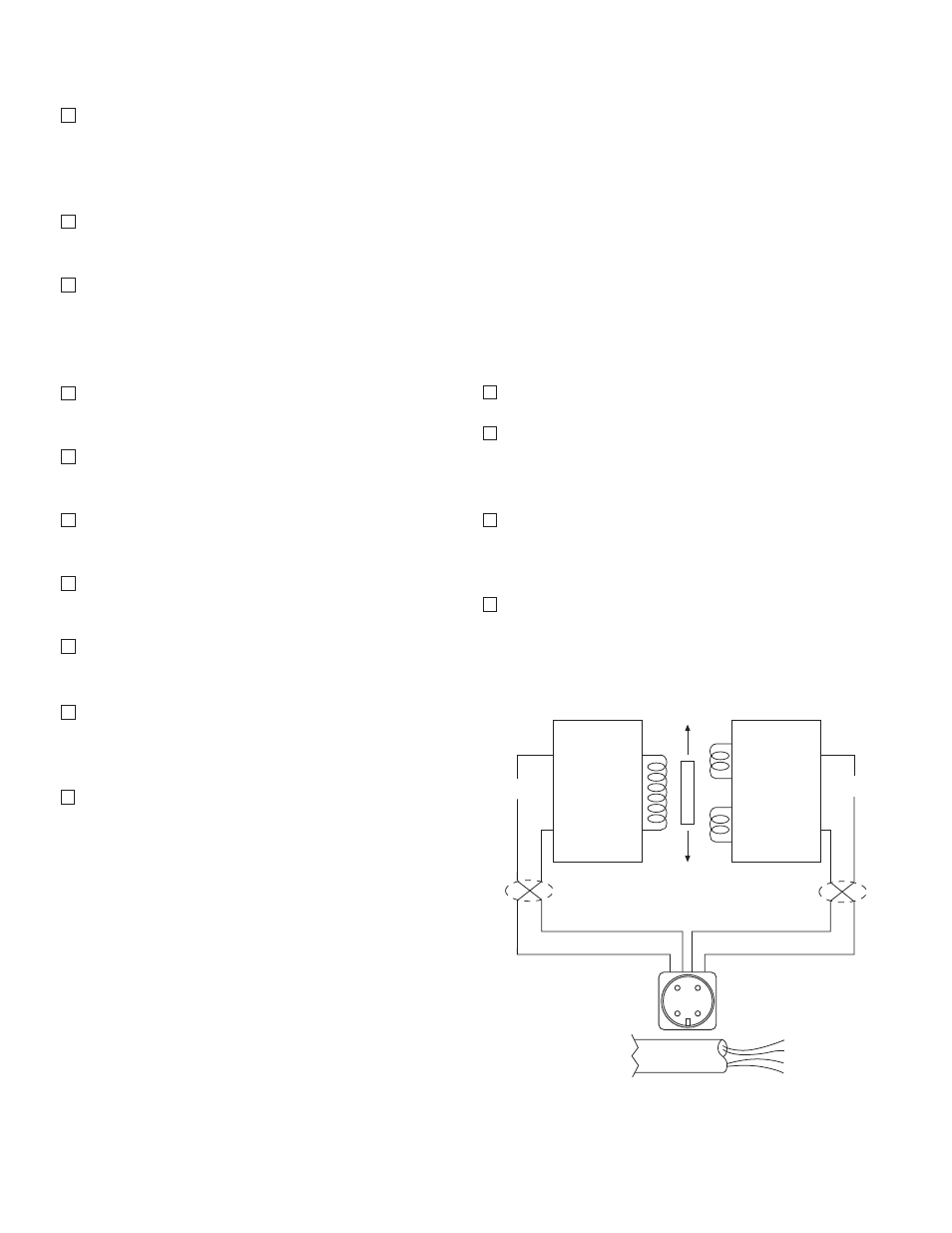
3. Observing correct polarity, connect the posi-
tive (+) input lead to Pin A and the negative
(-) input lead to Pin B. (See Figure 8)
4. Connect the positive (+) output lead to Pin D
and the negative (-) output lead to Pin C.
(See Figure 8)
Black - (2)
Red + (1)
Green (3)
Blue (4)
Input
Output
X Twisted Leads
A B
Oscillator
Demodulator
P1
S1
S2
X
X
When Supplied
with Cable
(1) Red
+ DC
(2) Black – DC
(3) Green
– Signal
(4) White + Signal
C D
B
A
C
D
Figure 8