Warner Electric ATT Brakes and Clutches User Manual
Page 3
3
Warner Electric • 800-825-9050
819-0341
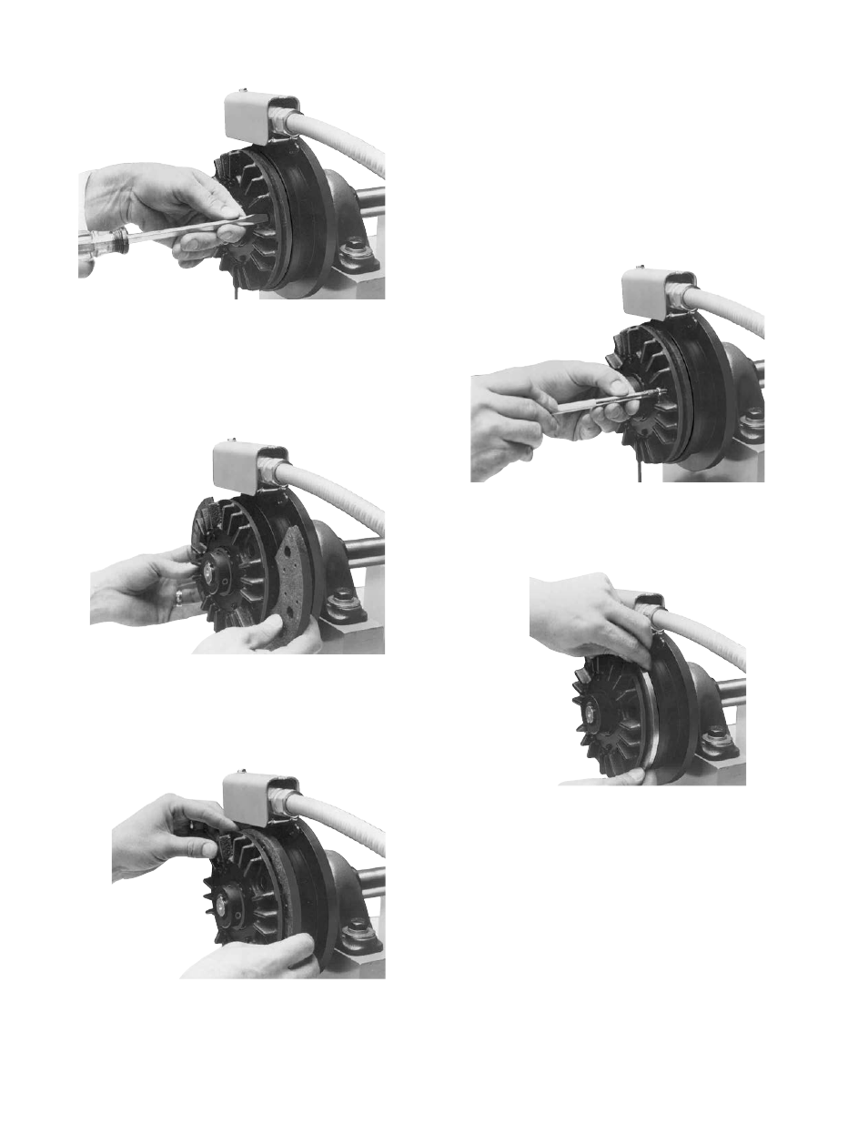
Figure 4
5. Lift out the worn friction material segments.
Assure that the autogap plate, detent ring
and spring remain in place on the clutch units
during this step. (See Figure 5)
Figure 5
6. Insert two new friction material segments.
The recessed holes should be facing away
from the magnet body. (See Figure 6)
Figure 6
7. Attach the new friction material segments to
the brake magnet or clutch rotor with the
screws through the appropriate access holes.
Apply one drop of Loctite
®
‚ (grade AA equiva-
lent) to each screw. (See Figure 7)
Note: Use
only the screws included with the repair kit
since any other screws may damage the
unit. Tighten screws to 18 to 22 inch
pounds torque.
Figure 7
8. Insert the two new armature segments. (See
Figure 8)
Figure 8
9. Attach the new armature segments to the
cast iron carrier with hex head capscrews,
lockwashers and washers. (See Figure 9)
Apply one drop of Loctite
®
‚ (grade AA or
equivalent) to each screw. Clean all hardware
to remove old Loctite‚ and dirt. Tighten to the
appropriate torque for your size unit.
- UNIBRAKE NEMA 4 (6 pages)
- UNIBRAKE (8 pages)
- ARC 2000 (16 pages)
- ARC Clutch_ZRC Top Load (18 pages)
- ZRC Clutch_ARC Top Load (18 pages)
- Dairy Cap Chuck (24 pages)
- Dairy Capping Headsets (10 pages)
- Autogap 475 & 650 (4 pages)
- Brushholder Installation (2 pages)
- Autogap 825-1225 (2 pages)
- Electro-Packs EP-170, 250, 400, 500, 825, 1000, 1525 (20 pages)
- Electro-Brake 375, 475, 650, 825, 1000, 1225 (20 pages)
- Electro-Clutch EC-375, EC-475, EC-650, EC-825, EC-1000, EC-1225 (20 pages)
- 5300-101-001 Collector Ring (2 pages)
- 5301-101-010 Collector Ring (2 pages)
- Brushholder Assembly and Mounting Dimensions (2 pages)
- SF_PB 400 (2 pages)
- SF_PB 250 (2 pages)
- Autogap 825-1525 (4 pages)
- Electro-Module EM-50, EM-100, EM-180, EM-210, EM-215 (22 pages)
- FB-375, 475, 650 (14 pages)
- 5200-101-012 Conduit Box Kit (4 pages)
- 5200-101-011 Conduit Box Kit (4 pages)
- 5200-101-010 Conduit Box Kit (4 pages)
- Recommended Electrical Installation Procedure for Warner Electric Clutches and Brakes (2 pages)
- EP-400 Vertical Mounting (2 pages)
- EP-250 Vertical Mounting (2 pages)
- Autogap 500 (4 pages)
- ER 825 and 1225 Normal Duty (16 pages)
- ER 825 and 1225 Heavy Duty (14 pages)
- ERS Electrically Released Brakes (6 pages)
- AT Brakes & Clutches Complete Brake Repair – On the Shaft, Sizes 25, 55, 115 (4 pages)
- AT Brakes (6 pages)
- AT Brake–Major Service Repair Instructions for Sizes 25, 55, 115 (9 pages)
- AT Clutch – Major Service Sizes 25, 55, 115 (12 pages)
- 5162-101-002 Conduit Box Kit (6 pages)
- Electrically Released Permanent Magnet Clutch Compatible Modules (4 pages)
- Electrically Released Motor Brake Module for EM-MBFB and EUM-MBFB (6 pages)
- Electrically Released Brake Module For EM-FBB and EUM-FBB (4 pages)
- Electrically Released Brake ER-375, ER-475, ER-650 (12 pages)
- Autogap 825-1525 Special Heavy Duty (4 pages)
- 5370-101-042 Conduit Box Kit (4 pages)
- Preassembled Clutch_Electrically Released Brake Module (7 pages)
- EUM-50_EUM-100_EUM-180_EUM-210_EUM-215 (16 pages)
- 5370-101-045 Conduit Box Kit (5 pages)