Warner Electric Gen 2 Electrically Released Motor Brake Module for EM-MBFB and EUM-MBFB User Manual
Page 2
2
Warner Electric • 800-825-9050
P-273-8 • 819-0531
Model
Part No.
EM 50-20MBFB-10
5370-169-249
EM 50-20MBFB-10, 24V
5370-169-248
EM 100-20MBFB-21
5370-169-254
EM 100-20MBFB-21,24V
5370-169-253
EM 180-20MBFB-21
5370-169-259
EM 180-20MBFB-21, 24V
5370-169-258
EUM 50-20MBFB-6
5370-169-263
EUM 100-20MBFB-12
5370-169-264
EUM 180-20MBFB-12
5370-169-265
Note: The model EUM is a vented style
housing which includes the cover kit to
enclose the housing. The model EM
is a vented style housing. They can be
enclosed by purchasing the optional
cover kit 5370-101-082. (See page 4 for details.)
Mounting Instructions
Step 1: Mounting the Brake to a Motor
The brake module (20MBFB) can be mounted
directly to the motor as follows:
A. Insert the key provided in the motor shaft
keyway. Prick punch the end of the motor
shaft keyway to prevent the key from sliding
out.
B. Align the motor shaft and key with the mating
shaft hole and key slot in the brake module.
If anti-fretting lubricant is used
on the motor shaft for future ease of removal,
ensure that any excess is wiped off before
unit assembly to avoid lubricant
contaminating the clutch or brake friction
faces.
C. Slide the module onto the motor shaft so the
module surface is snug against the motor
face.
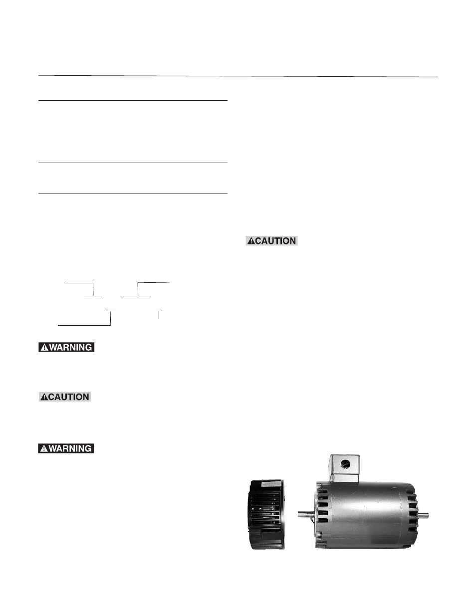
NOTE: Brake Module should slide freely
onto shaft and fit flush with motor C-face.
(Figure 1)
D. Secure the brake module (20MBFB) to the
motor C-face with the four (4) long hex head
capscrews provided. Tighten the four (4) bolts
alternately to ensure even alignment of the
module. Tighten them to 30-35 foot pounds.
Figure 1
W
arner Electric’s MBFB series of Electrically Released Brake Modules are designed for
brake only applications when mounted to the back of a NEMA C-face double shaft motor.
The fail safe brake engages when power goes off.
Model
Configuration
EUM 50-20MBFB-6
Size
Static Torque lb. ft.
Failure to follow these
instructions may result in product damage,
equipment damage, and serious or fatal injury
of personnel.
If brake is to be applied with the
brake output shaft in a vertical position
Warner Electric’s application engineering
should evaluate application.
The term “fail safe” describes a
brake that engages automatically when its full
power is shut off for whatever reason. The
term, as applied to brakes, designates a mode
of operation, not a guarantee of safety for the
equipment on which the brake is mounted and
for personnel who are near it.