Warner Electric Electric Wheel Brake 12-1_4 x 3-1_2 Installation Instructions User Manual
Page 2
2
Warner Electric • 800-825-9050
A-216 • 819-0244
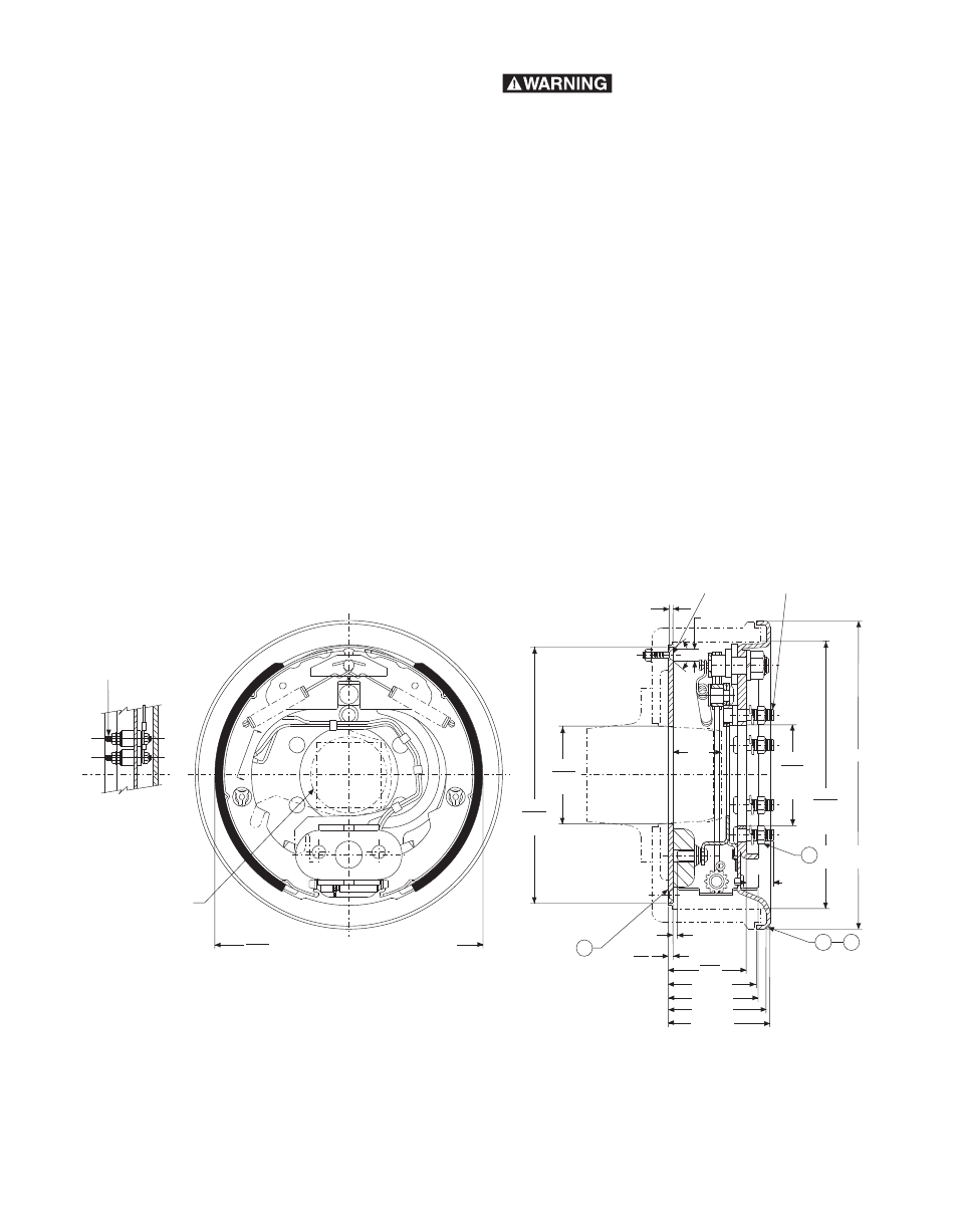
Dimensions when used with .224/.205 Armature, Warner Electric Part No. 110-0124
A
A
˚
14 1/8 dia.
12.260
12.250
finished
drum dia.
4.510
4.503
pilot dia.
4.515
4.490
dia.
11.750
11.715
dia.
.290/.265 Dia. (6) holes equally spaced on
11.000 dia. within .007 R. of true position
(C'sunk for 1/4 dia. 80∞ flat head machine
screws with nuts and lockwashers, or 80∞ flat head rivets)
.170 min.
1/2–20 UNF-2A, (6) req'd.
Equally spaced on 5.500 dia. within
.005 R. of true position to
4.510/4.503 pilot diameter
.540
dia. min.
2.125
max.
Torque to
71-79 ft. lb.
4
3
1
2
1.100 min.
.125 ref.
.224
.205
3.881 min.
4.068 max.
4.381 min.
4.752 max.
3.567
3.507
12.225
12.195
factory adjustment diameter over brake linings
Face View of Brake Assembly
(Drum and armature removed)
(2) 1/4 dia. terminal studs
Section A–A
The magnet arm will
clear a maximum axle
of 3 1/2" diameter
or a 3" square
positioned as shown
Contents
Dimensions . . . . . . . . . . . . . . . . . . . . . . . . . . . .2
Technical Specifications . . . . . . . . . . . . . . . . . .3
Installation Instructions
General . . . . . . . . . . . . . . . . . . . . . . . . . . . . .3
Preparing the Brake Mounting Surface . . . . .3
Installing on Axle Flanges . . . . . . . . . . . . . . .3
Installing the Brake . . . . . . . . . . . . . . . . . . . .4
Preparing the Brake Drum . . . . . . . . . . . . . .4
Adjusting the Brake . . . . . . . . . . . . . . . . . . . .5
Installing the Trailer Brake Wiring . . . . . . . . .5
Replacement Parts . . . . . . . . . . . . . . . . . . . . . .6
Towing Products Required with your
12-1/4" x 3-1/2" Brakes
Controller . . . . . . . . . . . . . . . . . . . . . . . . . . .8
Load Control . . . . . . . . . . . . . . . . . . . . . . . . .8
Front Axle Resistor . . . . . . . . . . . . . . . . . . . .8
Warranty . . . . . . . . . . . . . . . . . . . . . . .Back Page
Failure to follow these
instructions may result in product
damage, equipment damage, and
serious or fatal injury to personnel.
Right hand brake shown
Left hand brake opposite
Drawing No. I-26117