General – Warner Electric Electric Compressor Clutch Installation User Manual
Page 2
2
Warner Electric • 800-825-9050
P-1426 • 819-0392
Failure to follow these
instructions may result in product damage,
equipment damage, and serious or fatal
injury to personnel.
General
This compressor clutch has been developed
specifically for automobile air conditioning
applications. Properly installed, it will provide
maintenance free service. The clutch, using a
stationary field principle, does not require slip
rings or brushes.
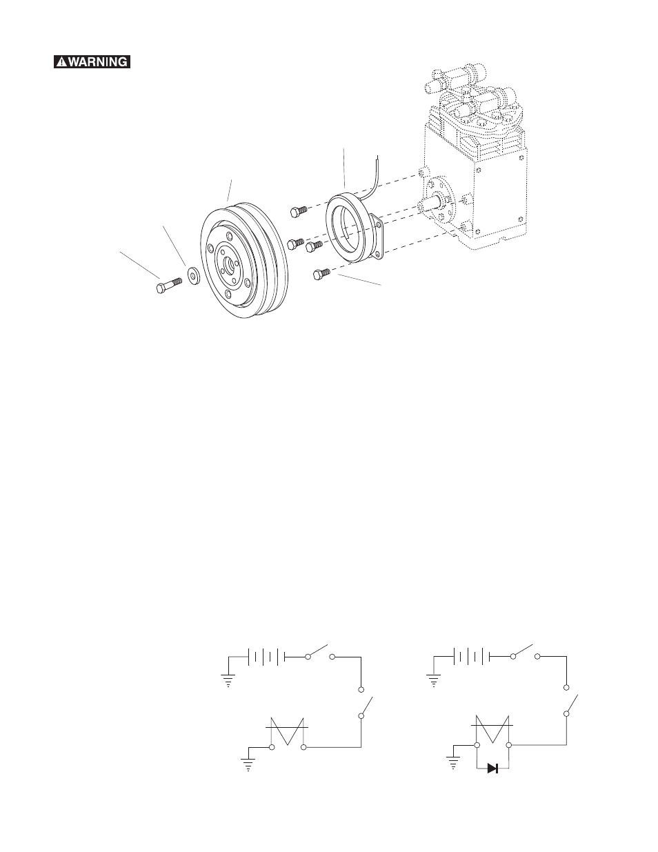
The clutch consists of two major components,
a stationary magnetic field assembly and a
rotor-pulley assembly. The field assembly is
mounted on bosses on the compressor. The
rotor-pulley assembly is mounted to the
compressor crankshaft and driven by V-belts
from the engine crankshaft pulley. Electricity
energizes the clutch field to couple the clutch
magnetically, thus driving the compressor.
De-energization of the field releases the clutch
and uncouples the compressor.
Compressor
Field Assembly
Capscrews
and
Lockwashers
Rotor Pulley
Assembly
Capscrew
Washer
1
2
4
5
3
Installation
Wiring
In most cases, the coil in the field assembly
has a single leadwire (hot) and is grounded to
the field shell. (See Figure 1)
Some newer applications however require the
use of a rectifier diode to protect delicate
electrical components. It is up to the installer
to determine if a diode is necessary.
If a diode is necessaary, one has been
provided with this clutch and must be
connected as directed on enclosed diode
installation instructions. (See Figure 2)
Note: If you are unsure a diode is needed for
your application, install it anyway.
Ignition
Switch
Battery
Clutch
Clutch
Switch
Coil Ground
Figure 1
Ignition
Switch
Battery
Clutch
Clutch
Switch
Coil Ground
Diode
Figure 2