Electrical connection, Wiring diagram – Warner Electric 1300-77 12 Volt Utility Controller for 4, 6 or 8 User Manual
Page 3
3
Warner Electric • 800-825-9050
P-1379 • 819-0094
Electrical Connection
1.
Electrical connection is required for all
installations. Approximately 25 ft. of
automotive-type multistranded 12 gauge
or heavier single wire with tough,
thermoplastic insulation meeting SAE
standard J558a is required. Note: When
towing a trailer which will carry variable
loads, or which is light weight when
compared with its brake capacity, a
Warner Electric Load Control, Part No.
1300-78, may be required to properly
proportion braking force between the
trailer and the towing vehicle. See Optional
Equipment, page 4.
2.
An electrical socket which mates with the
trailer power cable is to be installed in the
rear of the towing vehicle. Strip one end of
the hook-up wire and connect it to the brake
terminal of this socket.
3.
Secure a single length of wire from the
brake connection of the socket to the under-
side of the towing vehicle and lead it to the
engine firewall. Position the wire to insure
maximum protection from scraping on the
road surface in rough terrain, flying stones,
spray, etc. Also avoid attaching wires near
mufflers and exhaust pipes. Wires should be
clamped at frequent intervals.
4.
Remove a knock-out plug or cut a hole in
the firewall near the mounted controller.
5.
Cut the wire to a proper length for reaching
the controller. Strip the wire and feed it
through the firewall hole.
6.
Connect this wire to the blue brake lead wire
extending from the back of the
controller.
Note: Solder or crimp clamp connections
will be required when connecting all three
controller lead wires. Wrap electrician’s
tape around all bare wire joints. Do NOT
use twist-type connectors.
7. Making a chassis ground connection is the
next installation step. Strip one end of the
remaining length of hook-up wire and
connect it securely to the ground terminal of
the socket at the rear of the towing vehicle.
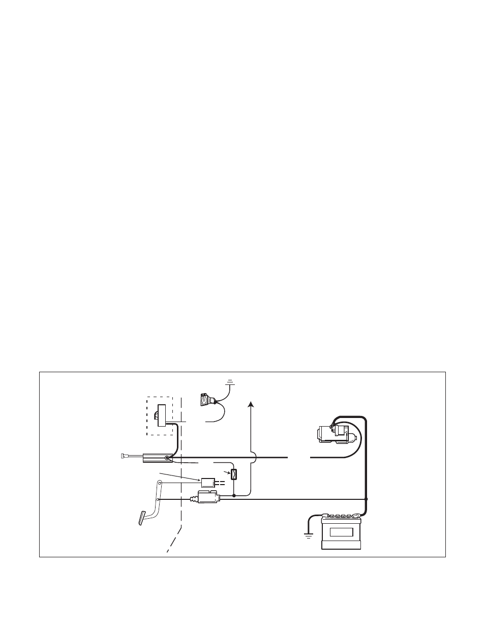
Figure 3
BLUE
SOCKET
TO STOPLIGHT
10 GAUGE WIRE
RECOMMENDED
LOAD CONTROL
1300-78
OPTIONAL
UTILITY CONTROLLER
MOUNTED ON DASH
MECHANICAL
STOPLIGHT
SIGNAL
STOPLIGHT
SWITCH
RED
FUSE
BATTERY
BLACK
10 GAUGE WIRE
RECOMMENDED
STARTER
Wiring Diagram