Warner Electric P620 User Manual
Page 4
4 Warner Electric Europe • +33 (0)2 41 21 24 24
P-2085-WE • 11/12
5
Pneumatic connection
5.1 Recommendations
The equipment must be supplied with filtered,
oiled compressed air.
Comply with the specified control pressure
(table 1) so as to ensure correct brake release
on the equipment.
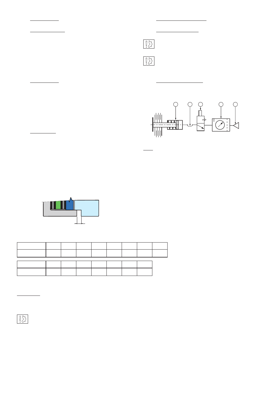
5.2 Connection diagram
This functional diagram is given as an indication:
Key:
1. Pressure source
2. Treatment unit consisting of: filter, pressure relief
and oiler simplified symbol)
3. Manual, mechanical, electrical or pneumatic control
3/2 distributor
4. Flexi pipe
5. Equipment to be controlled
4
Maintenance
4.1 Adjusting travel
To modify the travel “T” (see appendix), undo
the fixing bolt (909) about one turn, then set the
adjustment bolt (902) to the value necessary.
Lock the fixing bolts (909) to the correct torque
(see table 1). Check the value of the travel at
several points near the friction plate legs (348).
4.2 Maintenance
Wear in the linings causes an increase in the
travel. Before reaching maximum value (see
table 1), it is necessary to make an adjustment
(See above). Make several movements, motor
stopped, check the new value for the travel at
several points as described above.
4.3 Spare parts
After a number of adjustments, variable
depending on the size of the machinery and its
use, replacement of the fric tion disc or discs is
necessary when the value “ Y” for the interval
between the friction plate lugs (312) and the
cylin der (401) reaches the value in the table
below. To replace them, refer to paragraph 3-3.
A new adjustment of the travel is necessary
(see paragraph 4.1).
Important: Before refitting the cylinder onto the piston,
lightly lubricate the seals and contact surfaces with a
film of Molykote 55M or equivalent grease.
Take care not to damage the seals while re-
assem bling.
P520
10
20
50
100
200
400
800
1600
Y min. mm
0
0
0
0
0
2
P620
50
100
200
400
800
1600 3200
Y min. mm
0
0
0
0
3
Y
1
2
5
3
4
Y
1
2
5
3
4
Fig. 3