Warner Electric H420 User Manual
Page 5
Warner Electric Europe • +33 (0)2 41 21 24 24
P-2067-WE • 2/13 5
M
b
a
c
d
e
f
g
M
b
a
c
d
e
f
g
h
M
M
b
a
c
d
e
n
g
p
h
f
o
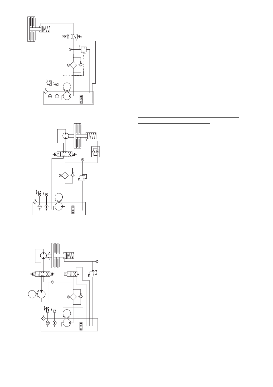
Figure 1: Basic circuit for multidisc brake with hydraulic release
a: Reservoir
b: Pump
c: Filter
d: Pressure gauge
e: Pressure limiter
f: Distributor
g: Brake
The brake is lubricated by splashed non renewed oil.
Figure 2: Hydraulic release, multidisc brake assembly in
open circuit with hydraulic motor
a: Reservoir
b: Pump
c: Filter
d: Pressure gauge
e: Pressure limiter
f: Distributor
g: Brake
h: Flow restricter with non-return valve
The distributor in central position causes the oil to return to the
reservoir and the brake to close. Going to one of the two other
positions causes the brake to open and the hydraulic motor to
rotate, in one or other direction, according to the position of the
slider.
Figure 3: Hydraulic release, multidisc brake assembly in
closed circuit with hydraulic motor
a: Reservoir g: Brake
b: Pump h: Pump
c: Filter n: Distributor
d: Pressure gauge o: Calibrated non-return valve
e: Pressure limiter p: Hydraulic motor
f: Distributor
The distributor for the hydraulic motor and brake are controlled
simultaneously causing the brake to release and the motor to rotate.
Figure 1
Figure 2
Figure 3