Warner Electric AT Clutches User Manual
Page 4
4
Warner Electric • 800-825-9050
P-217-1 • 819-0372
3. Through Bolt Mounting
Note: This method is suitable for pulleys and
sheaves with adequate radial wall thickness
to accommodate through holes.
a. Drill holes through the pulley or sheave
to match the tapped holes on the hub
shoulder of the clutch. The correct bolt
pattern can be found on page 7.
b. Align the through holes in the sheave or
pulley with the tapped holes on the hub
shoulder and gently tap until it seats
against the shoulder.
Note: Installing the keyway and snap ring
are not necessary if the sheave or pulley
is held in place by the through bolt
method.
c. Secure the pulley with capscrews, using
lockwashers or Loctite to assure thread
retention.
4. If used, install the Warner Electric conduit box
or conduit box/CBC-100 control combination in
accordance with instructions furnished with the
conduit box.
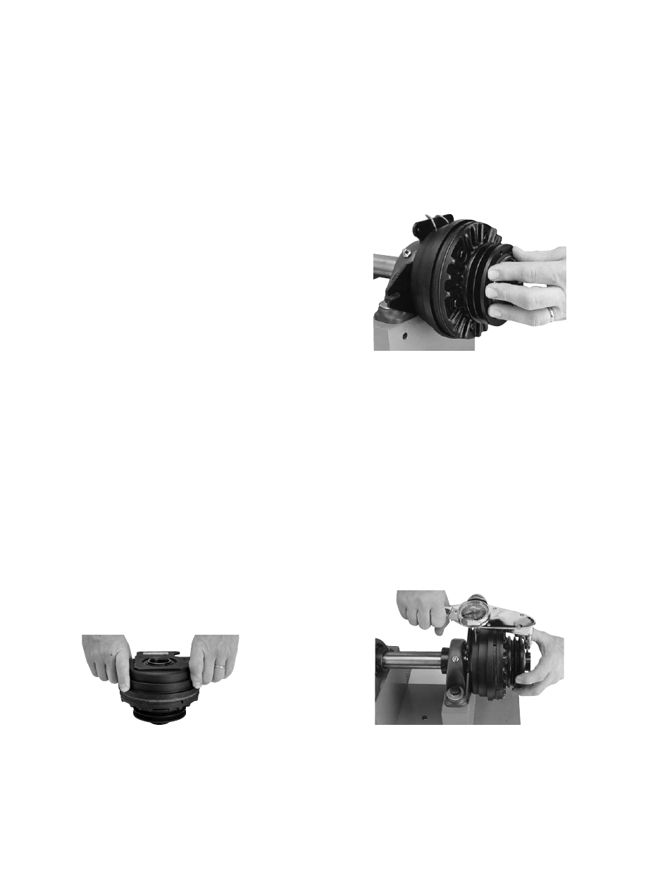
5. The Warner Electric patented Autogap™
automatically adjusts the proper operating gap
between the armature and friction face for the
life of these components. The proper gap is
approximately .050". If the armature and
friction face have moved during shipment,
reset the Autogap by pushing the friction face
against the armature. Release. The Armature
will spring back about .050" and the proper
gap is set.
6. Place the AT clutch onto its shaft, making
sure it is properly positioned over the shaft
key. If the clutch is to be mounted vertically,
it must be mounted with the armature fins
down, or improper operation will result.
Note: The Warner Electric special furnished
key must be used with ATC-25-7/8" bore
units.
7. Tighten the hub setscrews into the shaft to
the appropriate torque for your size unit:
Size
Torque
25
80 in.-lbs.
55
160 in.-lbs.
115
275 in.-lbs.
205
275 in.-lbs.
305
620 in.-lbs.
Assure proper alignment of driving and driven
sheave, pulley or sprocket before tightening
the set screws.