Warner Electric ERD–Electrically Released Brakes User Manual
Page 5
5
Warner Electric • 800-825-9050
819-0453
Options
• Manual Release - This option is recommend-
ed in applications where the brake needs to
be released by hand. This is ideal for gradu-
ally and safely lowering suspended loads in
the event of a power failure. Note: This option
requires magnet VAR 2.
• Dust Cover - This option is recommended for
use in environments which cannot be con-
taminated with brake friction dust and in
harsh dust, dirt, and humidity environments
where the brake is in danger from the con-
taminants.
• Friction Disc Carrier - Sizes 5 and 10 are
available with an optional synthetic material
carrier. Metallic disc carriers are standard for
all sizes.
• Friction Flanges - A friction flange is to be
mounted to the machine or motor frame if its
surface does not meet these specifications:
1. Cast iron or steel material
2. Hardness 150 HB
3. Smooth to 125 microinch
4. Flat to .002 inches
A friction flange is required if all of the specifica-
tions are not met. The correct flange is:
Thin friction flange
Used where surface is machined but unsuitable
for friction (eg. aluminum). Used in conjunction
with "Long screw kit". Only available through
size ERD 35 due to potential distortion with fric-
tional heat input.
Thick friction flange
Used in the absence of a suitable machined
mounting surface.
Mounting Screw Kits:
1. Short Screw Kit - supplied with the thick
flange for mounting on the external diameter
threaded holes.
2. Long Screw Kit - supplied with the thin flange
for mounting through the flange on the exter-
nal diameter holes. Can also be ordered sep-
arately for direct mounting without a flange.
Dust Cover
Airgap Adjustment
Spacer Screws
Friction
Disc Carrier
Holding Screws
Central Nut (VAR 2)
Hub
Magnet Assembly
Figure 1
ERD Brake Components
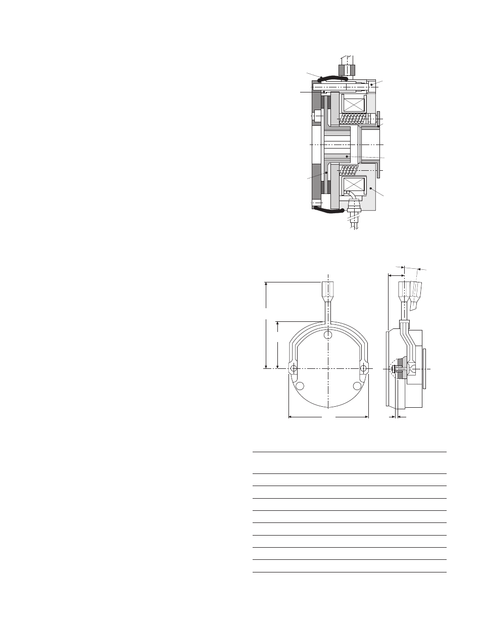
Figure 4 - Hand Release Lever Mounting
ERD
AA
BB
CC
EE
FF
Release
Size
Angle
5
3.86
2.09
0.67
3.46
.040
10
10
4.21
2.44
0.71
4.17
.040
9
20
5.08
2.99
0.98
5.20
.040
8
35
5.47
3.39
0.87
5.98
.050
8
60
7.44
4.09
1.57
6.54
.050
15
100
8.07
4.72
1.73
7.36
.050
15
170
9.57
5.51
2.09
8.78
.050
15
300 12.32
6.38
2.40
10.33
.050
20
AA
BB
EE
FF
CC
Release Angle