Warner Electric AT Brakes User Manual
Page 4
4
Warner Electric • 800-825-9050
819-0334
10. Your AT brake may not achieve its full
torque until after a short “break-in” period.
To break in the brake, cycle it on and off
under full load at operating speed a mini-
mum of ten times in quick succession.
Your AT brake is now ready to run.
Note: Depending on application break in peri-
od may be longer due to load and RPM, and
require more cycles.
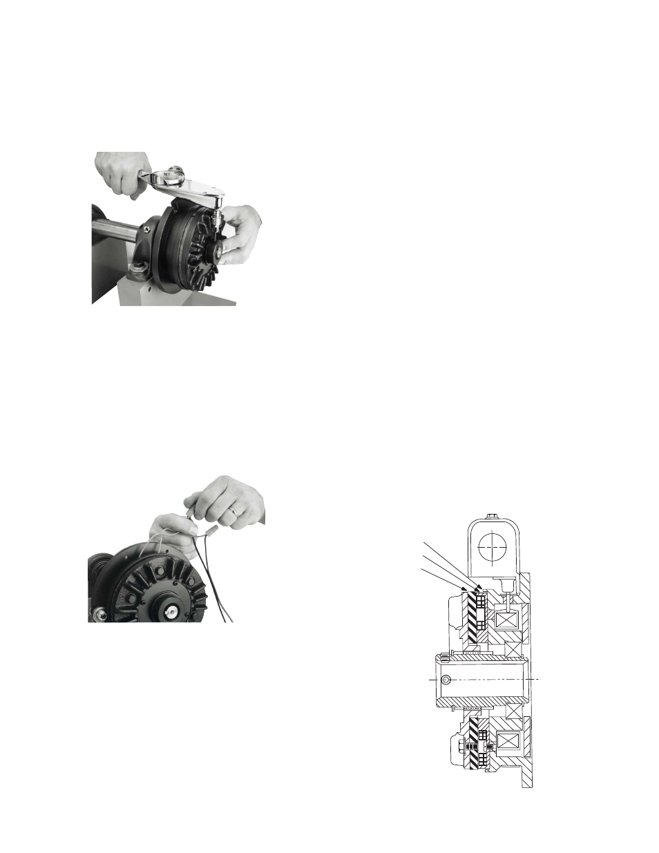
Wear Indication
Your AT brake should be visually inspected on a
periodic basis to determine if the wearing sur-
faces warrant replacement. The friction face and
armature should be replaced when the armature
reaches the wear indicator on the magnet shell.
If replacement is not made at this time, further
use will wear into the screw heads, making
removal and replacement of the friction facing
difficult. The drawing below illustrates the area
to be inspected.
When the friction surfaces are worn to this
point, replace with the appropriate friction face
replacement kit. All of the components needed
to refurbish the wearing surfaces of your brake
are provided in the replacement kit.
6. Tighten the set screws located in the hub to
the appropriate torque for your size unit:
Size
Torque
25
80 in.-lbs.
55
160 in.-lbs.
115
275 in.-lbs.
7. Attach the wires to the DC power source,
using wire nuts or other approved connecting
devices. Either wire can be connected to the
+ or - of the voltage source. If a Warner
Electric CBC-100 or other Warner Electric
control is used as the power source, follow
the connection diagram supplied with the
control. Assure that the voltage rating of the
brake is the same as the output rating of the
power source.
8. Your AT brake is now ready for its static test.
Apply DC voltage to the coil through the
brake control. The armature should pull
against the friction material face with an audi-
ble click.
9. Run the brake under its operating load.
Friction Face
Wear Indicator
Armature