Warner Electric AT Brakes & Clutches Complete Brake Repair – On the Shaft, Sizes 25, 55, 115 User Manual
Page 2
2
Warner Electric •
800-825-9050
P-1406 • 819-0335
Contents
Brake Repair . . . . . . . . . . . . . . . . . . . . . . . . . . . 2
Warranty. . . . . . . . . . . . . . . . . . . . . . . back cover
Failure to follow these
instructions may result in product damage,
equipment damage, and serious or fatal
injury to personnel.
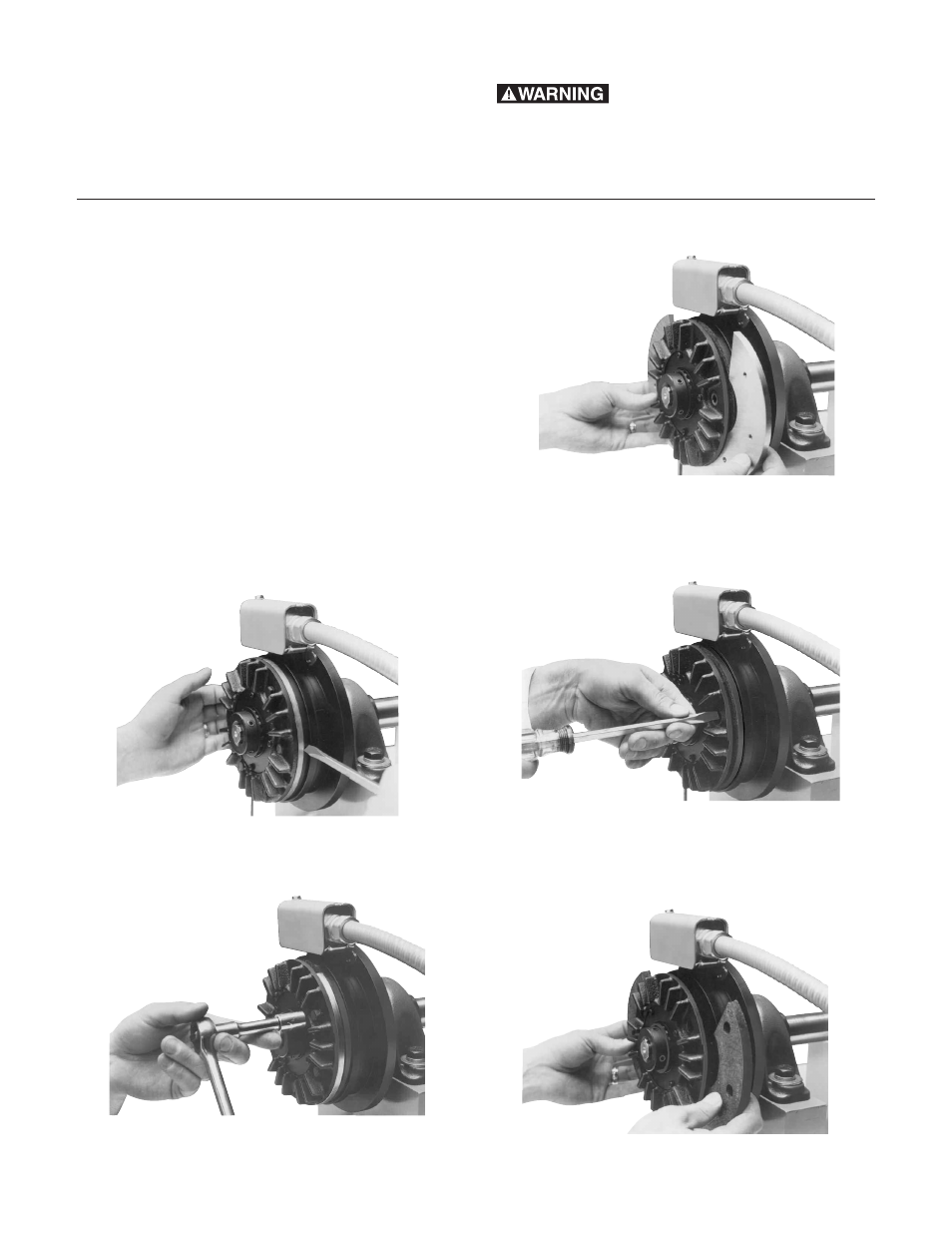
Complete Brake Repair - On the Shaft
The new AT design incorporates the latest in
advanced technology providing a rugged,
durable, patented design for long life, high cycle
rates and maximum heat dissipation. Patented,
easy to replace, friction surfaces extend the
design life for continued like-new performance.
The AT offers complete repair on the shaft
following ten easy steps. The repair can be
completed utilizing the parts in the friction face
replacement kit. The unit shown is a brake, but
steps apply equally to clutch repair.
1.
Move the brake or clutch armature away
from the magnet or field for disassembly
and reassembly.
2.
Remove hex head capscrews, washers
and lock washers to loosen the armature
segments from the cast iron carrier.
3.
Lift out the two worn armature segments.
4.
Remove the screws that attach the friction
material segments to the brake magnet or
clutch rotor through the appropriate access
holes.
5.
Lift out the worn friction material segments.
Assure that the autogap plate, detent ring
and spring remain in place on the clutch
units during this step.