Warner Electric 5200-101-010 Conduit Box Kit User Manual
Page 2
2
Warner Electric • 800-825-9050
P-1391 • 819-0198
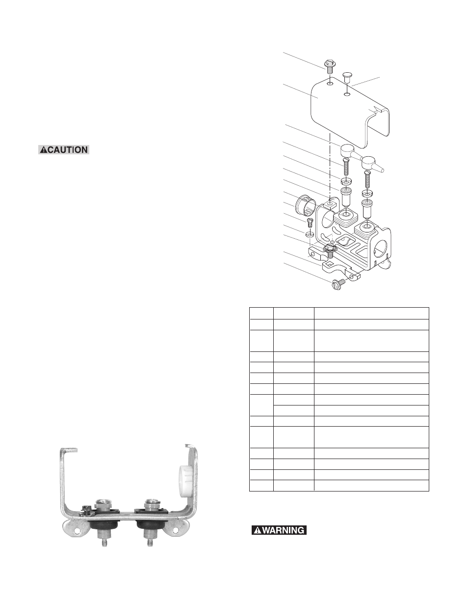
Parts List for kit 5200-101-010
Item Quantity
Part Name
1
1
Bracket
2
1
Screw, Hex, Washer Head
and Sems Conical Washer
3
1
Box, Conduit
4
3
Screw, Hex, Washer Head
5
1
Plug, Protective
6
2
Grommet, Wire
*7
2
Spacer No. 8 Thd.
2
Spacer No. 6 Thd.
8
2
Cap terminal
9
1
Screw, Hex, Washer Head,
Green
9-1
3
Terminal, Ring
10
1
Cover
11
2
Screw, No. 8 Brass
12
1
Plug, Protective
*The No. 6 spacers are required on Sizes 375, 400 and 475. All
others use No. 8.
4
10
8
11
9-1
*7
3
6
5
9
9-1
12
2
1
4
Components
Failure to follow these
instructions may result in product damage,
equipment damage, and serious or fatal
injury to personnel.
Introduction
Conduit box kit No. 5200-101-010 contains all
components needed to assemble a conduit box
for 375, 400, 475, 500, 650, ER-825, and ER-1225
clutches and brakes.
When properly installed, this conduit box is
designed to provide a proper means for field wiring
terminations. It conforms to the requirements of
Underwriters Laboratories.
Do not connect rigid conduit
directly to the conduit box. A minimum of 12” of
flexible liquid tight conduit or other suitable
flexible wiring with appropriate fittings is
required. Flexible wiring is required to prevent
side loading of bearing on bearing mounted
clutches and possible deformation or breakage
of the conduit box or clutch/brake components
during assembly.
Step 1
Assemble a customer supplied flexible wiring
connector into desired end of conduit box (3).
Press protective plug (5) into unused conduit hole.
Thread green washer head hex screw (9) into
round hole in base of conduit box. Place terminal
ring (9-1) over screw before inserting.
Snap two wire grommets (6) into square holes in
conduit box base. The grommet crowns should
be toward the outside of the box and the rubber
flanges should be on both sides of the conduit
box.
Push two terminal spacers (7) through rubber
grommets. Number 6 spacers fit in sizes 375, 400,
and 475. Sizes 500 to 1225 use number 8 spacers.
(See Figure 1)
Figure 1