Warner Electric Autogap 825-1525 User Manual
Page 2
2
Warner Electric • 800-825-9050
P-1366
•
819-0016
Primary Brake
SF - Stationary
Unit
PB
Field Clutch
Part
Magnet
Armature
Rotor
Field
Armature
Check
.010 T.I.R.
.010 T.I.R.
.006 T.I.R.
.006 T.I.R.
.006 T.I.R.
Concentricity
Outside
Drive
Pilot Dia.
Outside
Drive
Diameter
Pins
I.D.
Diameter
Pins
.006 T. I. R.
.006 T. I. R.
Squareness
Outer Pole
.006 T. I. R.
Outer Pole
.006 T.I.R.
of Face
Face
of Face
Face
Step 6. Slide the armature and the hub with
taperlock bushing over the shaft until the face of
the armature contacts the face of the magnet or
rotor. Move armature assembly to provide a
clearance of 1/16 inch between the armature
face and magnet or rotor face.
The assembly should be checked by pressing
the armature into contact with the friction face
and then releasing the armature. The armature
should spring back approximately 3/64-inch.
This gap wilI be automatically maintained
throughout the life of the unit.
Note:
During the assembly of the clutch or brake
components, the units must be checked for
concentricity and squareness to the shaft. This is
accomplished by using a dial indicator. The
following table gives the check points and
tolerances.
(See Figure 5)
of pin is against face of hub (since threads are
class No. 3, pins may seem to bind).
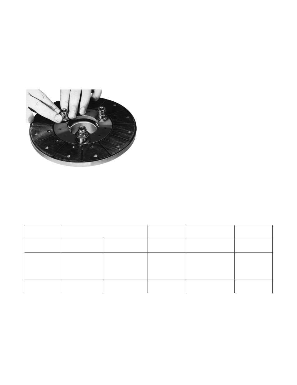
Step 5. Check to see that the armature is
completely compressed against the face of the
hub. To set the autogap, slide the detent spring
retainers against the armature face.
(See Figure 4)
Note:
This position must not be disturbed during
completion of assembly.
Figure 4
Figure 5 - Tolerance Table