Warning, Disassembly-assembly – Vestil ACH-100 User Manual
Page 13
8
When disassembling and assembling the ShopAir Hoist,
refer to the exploded view and the parts list on pages 10
thru 14. These show the proper relationship of the parts,
the names of the parts and the required quantities of the
parts. In addition, please observe the following:
1.
Needle bearings are pressed into the gear housing
(620-113), main frame (620-107), liftwheel (620-127)
and lower sheave wheel (620-162). Unless they are to
be replaced, do not attempt to remove these bearings.
2.
A liftwheel seal (620-108) is pressed into the main frame
(620-107) and a seal (620-130) is pressed into the end
of the liftwheel shaft (620-148). Be careful that these
seals are not cut or damaged during disassembly and
reassembly.
3.
Refer to page 7 for disassembly, inspection and
reassembly of the brake.
4.
Do not attempt to disassemble the Protector™ - refer to
page 7.
5.
Refer to page 6 for lubrication instructions.
6.
See next section for load chain removal and installation.
7.
Tighten the various screws as follows:
KEY-NO.
PART NAME
SEATING TORQUE
LB. IN.
NM
620-126
Pin Retainer Plate Screw
25
2.8
620-154
Motor Cover Screw
25
2.8
620-134
Gear Housing Screw
25
2.8
620-133
Brake End Cover Screw
25
2.8
620-168
Dead End Plate Screw
125
14.1
620-140
Hook Retainer Screw
10
1.1
620-157
Hook Block Screw
500, 600 and 1000 lbs.
(226, 272 and 453 Kg.)
(Double Reeved) units
125
14.1
250, 300 and 500 lbs.
(113, 136 and 226 Kg.)
(Single Reeved) units
50
5.6
620-510
Motor Screws
25
2.8
620-517
Valve Block Screws
25
2.8
620-518
Supply Bolt
50
5.6
8.
To remove the air motor (620-538), remove the motor
end cover (620-502) and motor end spacer (620-528).
Loose the valve bolts (620-518) enough to remove the
valve block assembly from the bottom of the motor.
Remove the two screws used to attach the motor to the
main frame (620-107) and carefully slide the motor shaft
out of the coupling (620-508). If necessary, refer to
page 9 for instructions for disassembling the motor.
9.
To install the air motor (620-538), slide the coupling (650-
508) onto the end of the motor shaft. Align splines on the
first pinion and shaft (620-131) and coupling and then
slide the motor into position. Secure the motor to the main
frame (620-107) using two screws. Attach the valve
assembly to the bottom of the motor using the two valve
bolts (620-518), making sure the O-rings are on the valve
bolts. Assemble the motor end spacer (620-528) and
motor end cover (620-502) to the main frame using three
screws.
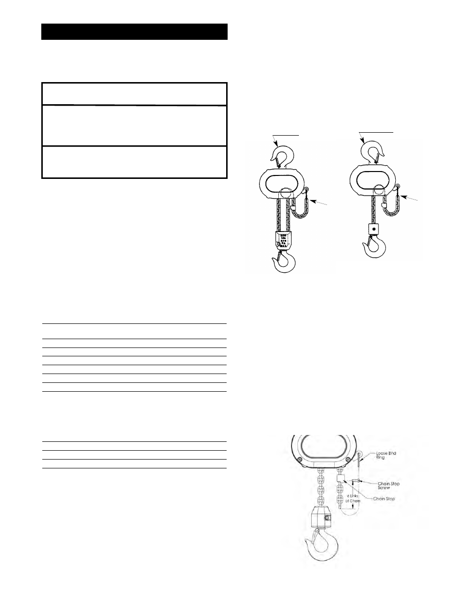
10. Properly install the upper hook as shown in Figure 11A,
then slide the hook retainer (620-139) into the cavity on
top of the hoist and secure it using hook retainer screw
(620-140). Tighten screw to a seating torque of 10 in. lbs.
(1.1 NM).
11. After reassembly, test the unit per instructions on page 9.
LOAD CHAIN REMOVAL/INSTALLATION
1.
If unit has a chain container, remove it from the chain
guide.
2.
Remove the chain stop (620-146), Depress “DOWN” ( )
lever and run chain out of hoist.
3.
Feed a short length of soft wire through the opening
between the chain guide (620-141), and stripper (620-143)
until it comes out of the hoist. Remove the wire and attach
the chain stop as shown below. On units with chain
container, place the chain stop and loose end of chain in
chain container. Attach chain container to chain guide.
4.
Jog the “UP” ( ) lever while pulling on the free end of wire
until the chain comes out of the hoist. Remove the wire
and attach the chain stop as shown below. On units with
chain container, place chain stop and loose end of chain
in chain container. Attach chain container to chain guide.
DISASSEMBLY-ASSEMBLY
F
Fiig
gu
urre
e 1
12
2.. A
Atttta
ac
ch
hiin
ng
g L
Lo
oo
os
se
e E
En
nd
d o
off C
Ch
ha
aiin
n
ShopAir
ShopAir
Hook Opening
Away From
Loose End
Hook
Opening
Towards
Loose End
Loose
End
Loose
End
F
Fiig
gu
urre
e 1
11
1.. H
Ho
oo
ok
k P
Po
os
siittiio
on
n
L
!
WARNING
Components such as motors, valves, lines,
filter/lubricators located after a closed shut-
off valve can contain pressurized air.
Disassembly in this state can cause injury.
Bleed the stored air by repeatedly
depressing the pendant paddles.