TREND IQView.._RPM User Manual
Page 2
2
IQView../RPM Installation Instructions TG200712 Issue 1/F 10/01/07
IQView../RPM
Installation Instructions
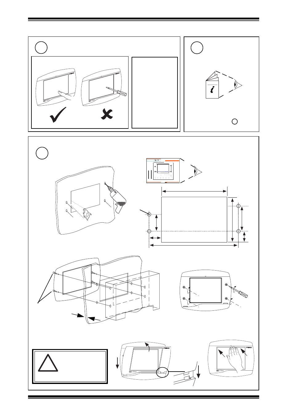
3.1 Installation - Mounting
(continued)
Care of Touch Screen
3
Clean Screen
Remove dust and
grease regularly
by wiping gently
with a soft cloth
such as that used
for spectacles
Use IQVIEW/NDP
ADAPTOR PLATE
4
if fixing in place of NDP in panel
IQVIEW/NDP ADAPTER PLATE
Installation Instructions TG200822
Jump to step 6
Mount Unit
5
a
b
c
d
view from front
view from rear
view from front
4 x M4 x 12 mm
screws provided
!
WARNING
Ensure correct sized
screws are used.
Failure to comply could
view from front
6 mm (0.24”)
maximum
1 - 1
IQVIEW/P ANEL Installation Instructions - Template TG200723 Issue 1/A 5/11/03
Installation Instructions - T emplate
IQVIEW/PANEL
Touch Screen Display
Important: Retain these instructions
IQVIEW/P ANEL
Installation Instructions - T emplate
Trend Control Systems Ltd reserves the right to revise this publication from time to time and make changes to the content hereof
without obligation to notify any person of such revisions or changes.
Trend Control Systems Ltd P.O. Box 34 Horsham Sussex RH12 2YF England Tel:+44 (0)1403 211888 Fax:+44 (0)1403 241608 www.trend-controls.com
10 cm
4"
NOTE: Print to size.
Check dimensions below
132 m m (5.2" )
1
0
3
mm
(4
.0
6
"
)
disp lay cuto ut clearance d im en sion s
cu tou t for display
A
A
A
A
A
m ou nting ho le centres
VIEW FROM FRONT
IQView../RPM template
TG200723
132 mm (5.2”)
27.5 mm
(1.08”)
58 mm
(2.28”)
70 mm (2.76”)
17 mm
(0.67”)
103 mm (4.06”)
4 holes Ø 5 mm
183 mm (7.2”)
e
cause damage to the unit.