Installation instructions t/pi/160, Installation – TREND T_PI_160 User Manual
Page 3
3
T/PI/160 PRT Immersion Temperature Sensor Installation Instructions TG100310A Issue 3/C 25/06/07
Installation Instructions
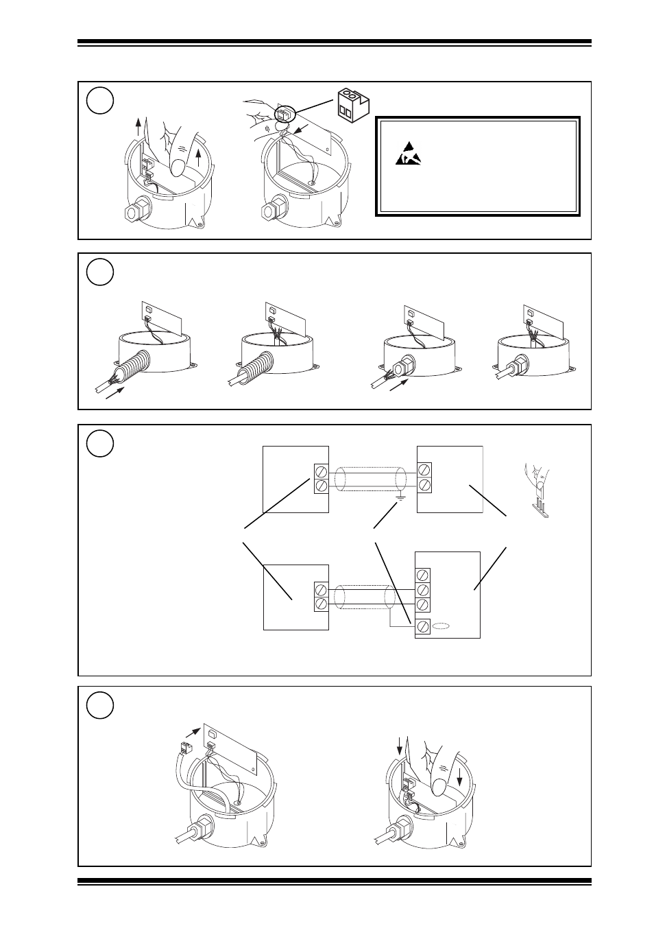
T/PI/160
Remove connector
7
INSTALLATION
(Continued)
Insert cable
8
Wire to controller
9
Replace Connector
10
Caution: This unit contains static sensitive
devices. Suitable anti-static
precautions should be taken
throughtout the operation to prevent
damage to the units.
BS EN100015/1 Basic Specification:
protection of electrostatic sensitive devices.
either use M20 flexible conduit
or use M16 cable gland
IQ1xx, IQ2xx
polarity independent
Sensor
24 Vdc
IN
Terminate screen at IQ end only
Analogue input channel
linked for current (I)
I
IQ system TP/I/22/HF/200 (Belden
8761) cable recommended.
Terminal size 0.5 to 2.5 mm
2
(14 to 20
AWG)
IQ3
Sensor
0 (0 V)
N (in)
+ (24 V)
Note that if connecting to an IQ22x controller (including /ADL or /OC), do not connect directly to C (+24V), instead
connect to AUX+ (+24V).
- PN-VPC (2 pages)
- DPCM (24 Vac_dc) (4 pages)
- 2VID (24 Vac_dc) (4 pages)
- 6RM_24VAC (4 pages)
- 3RM_24VAC (4 pages)
- 2RM_24VAC (4 pages)
- 2SRM (24 Vac_dc) (4 pages)
- SRMAC (4 pages)
- 4DiX_24Vac (4 pages)
- AD20-xx (4 pages)
- AD05-xx (4 pages)
- AL0406-P-SU (2 pages)
- AL0206-P-K (2 pages)
- ACCA_VB_ADK (1 page)
- AT0102-24 (2 pages)
- V162X (4 pages)
- V584 (2 pages)
- V583 (2 pages)
- NXIP (8 pages)
- NXNI (8 pages)
- NX Variable Speed Drives (136 pages)
- NXL Variable Speed Drives (12 pages)
- XW_R_IQ (4 pages)
- ACCW_RW_IQ (4 pages)
- TW_S (4 pages)
- TW_P (4 pages)
- PCW_... (4 pages)
- OCC_U (4 pages)
- LLO (4 pages)
- LLS (4 pages)
- WS_R (2 pages)
- WS_S, _SD (4 pages)
- AQ_S (4 pages)
- AQ_D (4 pages)
- DPSL (4 pages)
- DPSA (4 pages)
- PIl3 (4 pages)
- DPIL (4 pages)
- DPIA (2 pages)
- HT_O (8 pages)
- HT_D (4 pages)
- HT_S (4 pages)
- T_FS (4 pages)
- T_FG (4 pages)
- T_AV (4 pages)