2 mid-bus probe retention, 3 probe connection to analyzer, Mid-bus probe retention – Teledyne LeCroy PCI Express 3.0 Mid-Bus Probe User Manual
Page 9: Probe connection to analyzer
Teledyne LeCroy
PCIe 3.0 Mid-Bus Probe Installation Guide
Version 1.2
9
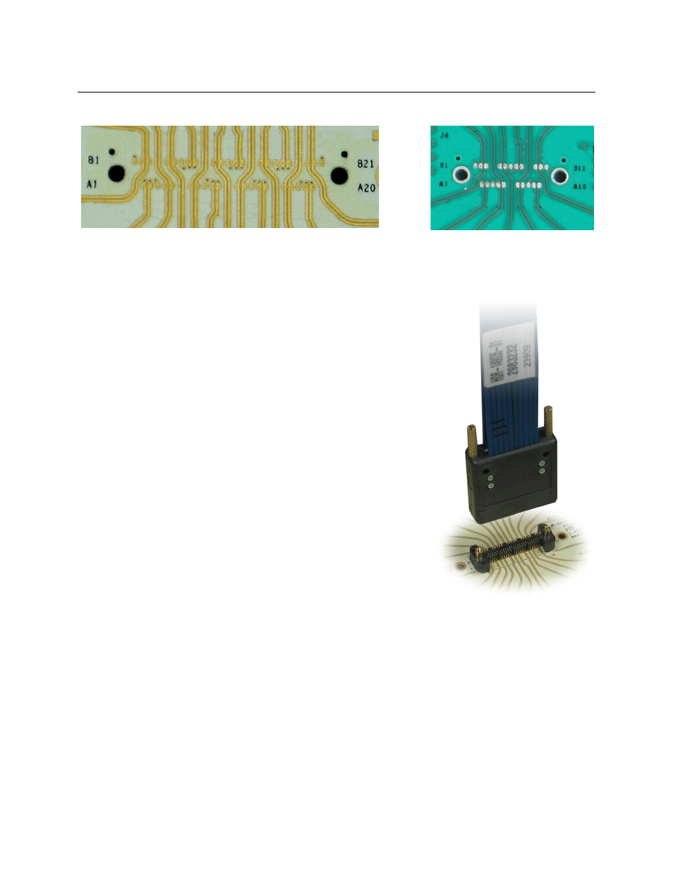
The PCB layout of a PCIe 3.0 mid-bus footprint would look as follows:
Full-Size PCIe 3.0 Probe Footprint Half-Size PCIe 3.0 Probe Footprint
3.2 Mid-bus Probe Retention
To prepare a circuit board for PCI Express mid-bus probing, the mid-
bus footprint has to be laid out onto the target system board and a
probe connector has to be attached to the board. Attachment of the
probe connector is simple and quick. There are two through-hole
screws and one protrusion key underneath the probe connector.
Align the key of the probe connector with the keying/alignment hole in
the mid-bus footprint on the target system board, and connect the
small screws (supplied) through the PCB and into the threaded holes
on the underside of the Mid-bus connector module, and tighten the
screws to ensure good contact between the contacts of the connector
and the pads on the PCB. The mid-bus probe can then be attached
to the target system board through the probe connector to provide
mechanical support for pin-to-pin alignment. The mid-bus cable has 2
retention screws that connect to the probe connector to hold the probe
in place.
NOTE: The attachment screws supplied will provide secure
attachment for most PCB designs. If the PCB is very thick, the
screws may not be long enough to pass through the PCB and
securely attach the Mid-bus connector module, in which cases longer
screws will be needed. The screws supplied are 5mm long
(McMaster-Carr P/N 91292A005), and longer lengths can be obtained
directly from McMaster-Carr in 6mm (91292A006), 8mm
(91292A008), or longer lengths as needed.
The probe connector should not be confused with a PCB connector because it is not part of the electrical
circuits of either the target system or the probe.
PCIe 3.0 probe connectors can be purchased through Teledyne LeCroy:
• Full-size: P/N PE047UIA-X
• Half-size: P/N PE054UIA-X
3.3 Probe Connection to Analyzer
The bus signals captured by the mid-bus probe are connected to a mid-bus probe pod for amplification.
This reduces the load imposed by the mid-bus probe on the target system, while allowing a longer cable
to attach to the Teledyne LeCroy PCI Express protocol analyzer. The Teledyne LeCroy PCI Express
protocol analyzer can then interpret these signals for full decoding and protocol analysis.