Adjust r24, gain – Teledyne LeCroy AP015 User Manual
Page 16
ADP015 Current Probe
12
922254-00 Rev A
Adjust R24, Gain
1. With the AP015 Current Probe removed from any signal and the slider
returned to the LOCKED position, degauss the probe by pressing the
DEGAUSS button (located on the coupling menu) twice.
2. Connect the AP015 to the 50 Turn loop, and set the oscilloscope vertical
scale to 20 A/div.
3. With the power supply set to 0 V, press the 'Null' button of the
multimeter measuring the probe voltage to subtract the probe's offset
voltage from the measurement. (If the multimeter being used does not
have this capability, the offset value can be manually subtracted from
the probe output values measured).
4. Increase the power supply voltage until the voltage measured at the
'Current Sense' terminals is approximately 100 mV. (This corresponds to
10 A at the probe head).
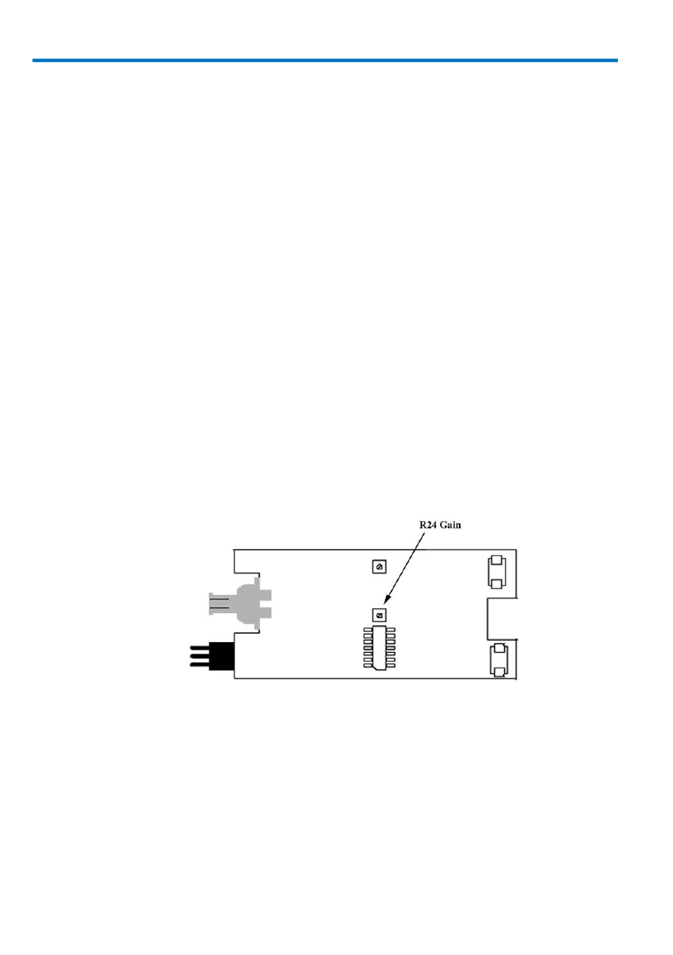
5. Carefully adjust R24 until the value measured by the multimeter
measuring the probe output is equal to 10x the value measured by the
current sense meter. (There are two adjustments on the circuit board;
R24 is the one farther from the board edge).
Figure 2, Gain Adjustment Location
6. After adjustment, calculate the accuracy (as in steps 15, 16, and 17
above) to confirm that the probe is measuring better than 1% accuracy.
7. Insert and tighten the two screws that secure the end panel to the
ProBus interface housing. Avoid over tightening the screws, as the cover
may warp.
8. Repeat the Performance Verification procedure to ensure compliance
with the warranted specifications.