KB Electronics KBMA-24DF User Manual
Page 4
See Figure 1. Also see Section 4 – Important Application Information, on page 13.
WARNING! Disconnect main power before making connections to the drive.
Note: It is recommended that both Feed-Through Bushings be used to connect the drive. If signal wiring (for the
Run/Fault Relay Output Contacts or for a remote Main Speed Potentiometer) is required, it is recommended that
the extra Feed-Through Bushing (supplied with the drive) be used to replace the center Hole Plug. Standard 3/4”
fittings (not supplied) can also be used in lieu of the Feed-Through Bushings.
1.1
MOUNTING INSTRUCTIONS – See Section
5, on page 14.
1.2
AC LINE INPUT CONNECTION – Connect
the single-phase AC line input to Terminal
Block TB1 (Terminals “L1”, “L2”), as shown
in Figure 1. See Section 6.1, on pages 14
and 15.
Application Note – Do not connect this
drive to a GFCI. If operation with a GFCI
is required, contact our Sales Department.
Note: The drive is factory set for 208/230
Volt AC line input (Jumper J1 not installed).
For 115 Volt AC line input, install Jumper
J1 (supplied). See Section 7.1, on page 16.
1.3
AC LINE FUSING – It is recommended that a
fuse(s) or circuit breaker be installed in the AC line. Fuse each conductor that is not at ground potential.
For the recommended fuse size, see Table 3, on page 9. Also see Section 6.1, on pages 14 and 15.
1.4
GROUND CONNECTION – Connect the ground wire (earth) to Terminal Block TB1 (Terminal “GND”),
as shown in Figure 1, above.
1.5
MOTOR CONNECTION – Connect the motor to Terminal Block TB1 (Terminals “U”, “V”, “W”), as shown in
Figure 1, on page 4. (Special reactors may be required for cable lengths over 100 ft. (30 m) – consult our
Sales Department.). See Section 6.3, on page 15.
4
1
QUICK-START INSTRUCTIONS
Important – You must read these simplified instructions before proceeding. These instructions are to be used
as a reference only and are not intended to replace the details provided herein. You must read the Safety
Warning, on page 5, before proceeding.
Note: This drive contains bus capacitors which must be reconditioned if the drive has been in storage for over
1 year. To recondition the bus capacitors, apply the AC line, with the main speed potentiometer set to zero, for
a minimum of 30 minutes.
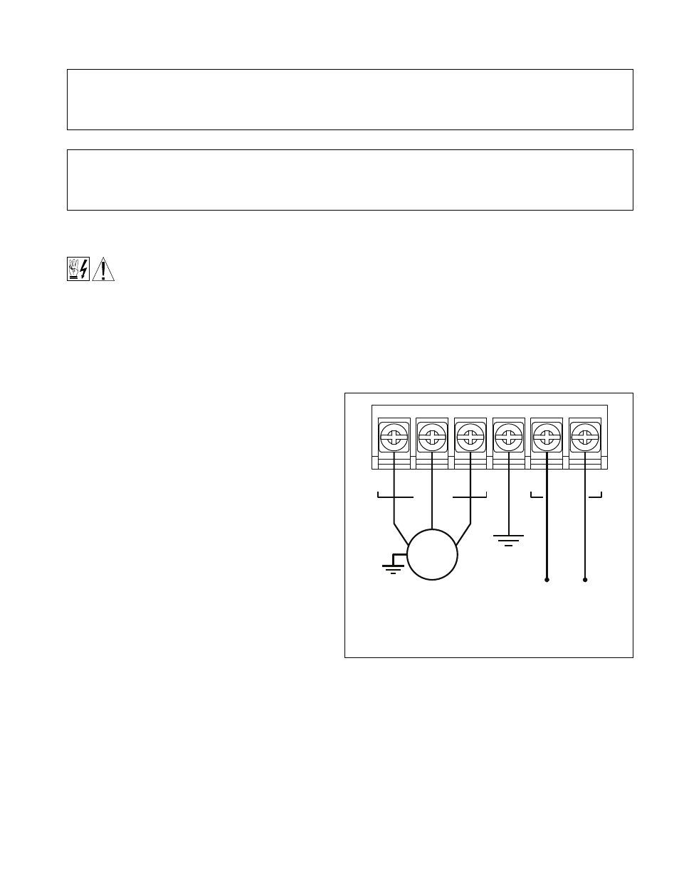
FIGURE 1 – QUICK-START CONNECTION DIAGRAM
115* or 208/230 Volt
Single-Phase AC Line Input
see Section 6.1, on pages 14 and 15.
* For 115 VAC line, install Jumper J1 (supplied).
3-Phase, 208/230 Volt
AC Induction Motor
see Section 6.3, on page 15.
AC LINE
MOTOR
Motor
TB1
U
V
Ground (Earth)
see Section 6.2,
on page 15.
GND
W
L1
L2