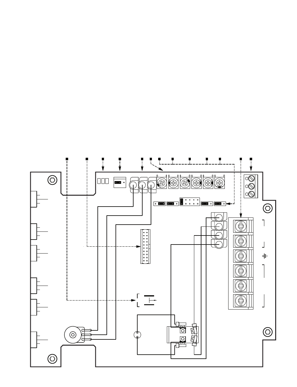
Figure 4 – drive la yout – KB Electronics KBMA-24DF User Manual
Page 12
12
CON2:
Used for optional Forw
ar
d-Stop-Reverse Switc
h.*
* The optional Forw
ar
d-Stop-Reverse Switc
h is r
equir
ed for Manual Start.
Main Speed Potentiometer
Ter
minals (P1,
P2,
P3).
Adjustable
Tr
impots (CL
, M
AX,
MIN
, A
CCEL,
DECEL,
COMP).
J4:
1X or up to 2X Rated Motor RPM Ope
ra
tion.
J6:
"Run" or "Fault" Output Relay
.
J3:
A
utomatic or Manual Start and Reset Oper
ation.*
TB1:
AC Line Input,
Moto
r,
Gro
und,
and connections. See Figur
e 7,
on page 15.
J5:
60 Hz or 50 Hz Motor Oper
ation.
TB2:
Run/Fault Relay Output Contacts.
J2:
Motor Horsep
ow
er.
Jumpers and trimpots ar
e sho
wn in factor
y set positions.
CON1:
Used to connect optional accessories to the drive
.
Install jumper for 115
Volt
AC line input. See Figu
re
9,
on page 16.
J1:
A
C Line Input
Voltage selection.
Diagnostic LEDs (Po
wer On,
Status,
Overload).
Main Speed P
otentiometer
(F
ront
Vi
ew)
Pa
nel Mounted
Violet
Orange
White
Pilot Lamp
Pa
nel Mounted
On/Off
AC Line Switch
(Back
View)
Pa
nel Mounted
Black
Blue
Blue
Black
White
White
L1B
L1A
L2A
L2B
CON1
115VAC
J1
J1-A
A
B
J1-B
U
GND
V
W
L1
L2
TB1
MOTOR
AC LINE
N.O.
COM
N.C.
TB2
OL
ON
ST
F
R
S
CON2
P 1
P 2
P 3
J6
FL
T
RU
N
FREQ
50HZ
60HZ
J5
J3
J2
1/2
1/8
1/4
3/4
1HP
MUL
T
AUTO
1X
J4
2X
MAN
ACCEL
C
M
P
E C
C
O
D
COMP
DECEL
N
C
A
I
M
M
X
A
C
L
MIN
MAX
CL
FIGURE
4
–
DRIVE
LA
YOUT