KB Electronics KBMA-24DF User Manual
Page 21
11 TRIMPOT ADJUSTMENTS
The drive contains trimpots which are factory set for most applications. See Figure 4, on page 12, for the location
of the trimpots and their approximate factory calibrated positions. Some applications may require readjustment
of the trimpots in order to set the drive for a specific requirement. The trimpots may be readjusted as described
below.
WARNING! If possible, do not adjust trimpots with the main power
applied. If adjustments are made with the main power applied, an
insulated adjustment tool must be used and safety glasses must be worn.
High voltage exists in this drive. Fire and/or electrocution can result if caution
is not exercised. Safety Warning, on page 5, must be read and understood
before proceeding.
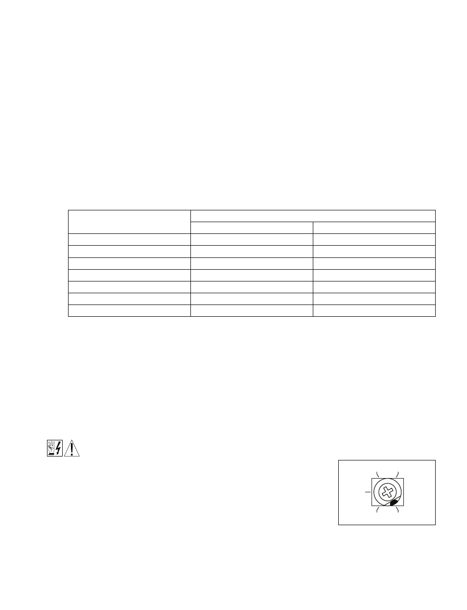
11.1 MINIMUM SPEED (MIN) – Sets the minimum speed of the motor. The MIN
Trimpot is factory set to 0% of frequency setting. For a higher minimum
speed, setting, rotate the MIN Trimpot clockwise. See Figure 17.
21
10.1 PILOT LIGHT – Located on the front cover. The Pilot Light will illuminate orange when the AC line is applied
to the drive and the On/Off AC Line Switch is set to the “ON” position.
10.2 POWER ON LED (ON) – Located on the PC board. The “ON” LED will illuminate green when the AC line is
applied to the drive and the On/Off AC Line Switch is set to the “ON” position.
10.3 STATUS LED (ST) – Located on the PC board. The “ST” LED is a green LED, which provides
indication of a fault or abnormal condition. The information provided can be used to diagnose an installation
problem such as incorrect input voltage and drive output miswiring. It also provides a
signal which informs the user that all drive and microcontroller operating parameters are normal.
Table 6 summarizes the “ST” LED functions.
10.4 OVERLOAD LED (OL) – Located on the PC board. The “OL” LED is a red LED, which provides
indication of an overload condition. Table 6, summarizes the “OL” LED functions.
Drive Operating Condition
LED and Flash Rate
1
Information
ST (Green)
OL (Red)
Normal operation
Slow Flash
Off
Overload (120% – 160% Full Load)
Off
On
2
I
2
t (Drive Timed Out)
Off
Quick Flash
Short Circuit
Off
Slow Flash
Undervoltage
Quick Flash
3
On
Overvoltage
Slow Flash
3
On
Stop
On
On
TABLE 6 – DRIVE OPERATING CONDITIONS & LED INDICATIONS
Notes: 1. Slow Flash = 1 second on and 1 second off. Quick Flash = 0.25 second on and 0.25 second off. 2. When the Overload is removed,
before the I
2
t times out and trips the drive, the “ST” LED will flash green and the “OL” LED will turn off. 3. In Manual Restart Mode, when the
Undervoltage or Overvoltage condition is cleared, the “ST” and “OL” LEDs will flash red / (red and green) / green.
MIN
30
15
0
35
40
FIGURE 17 – MINIMUM SPEED
TRIMPOT RANGE
(Shown Factory Set to 0%
Frequency Setting)