IDEC DS2_Series User Manual
Page 40
Instruction manual
DS2 series
39
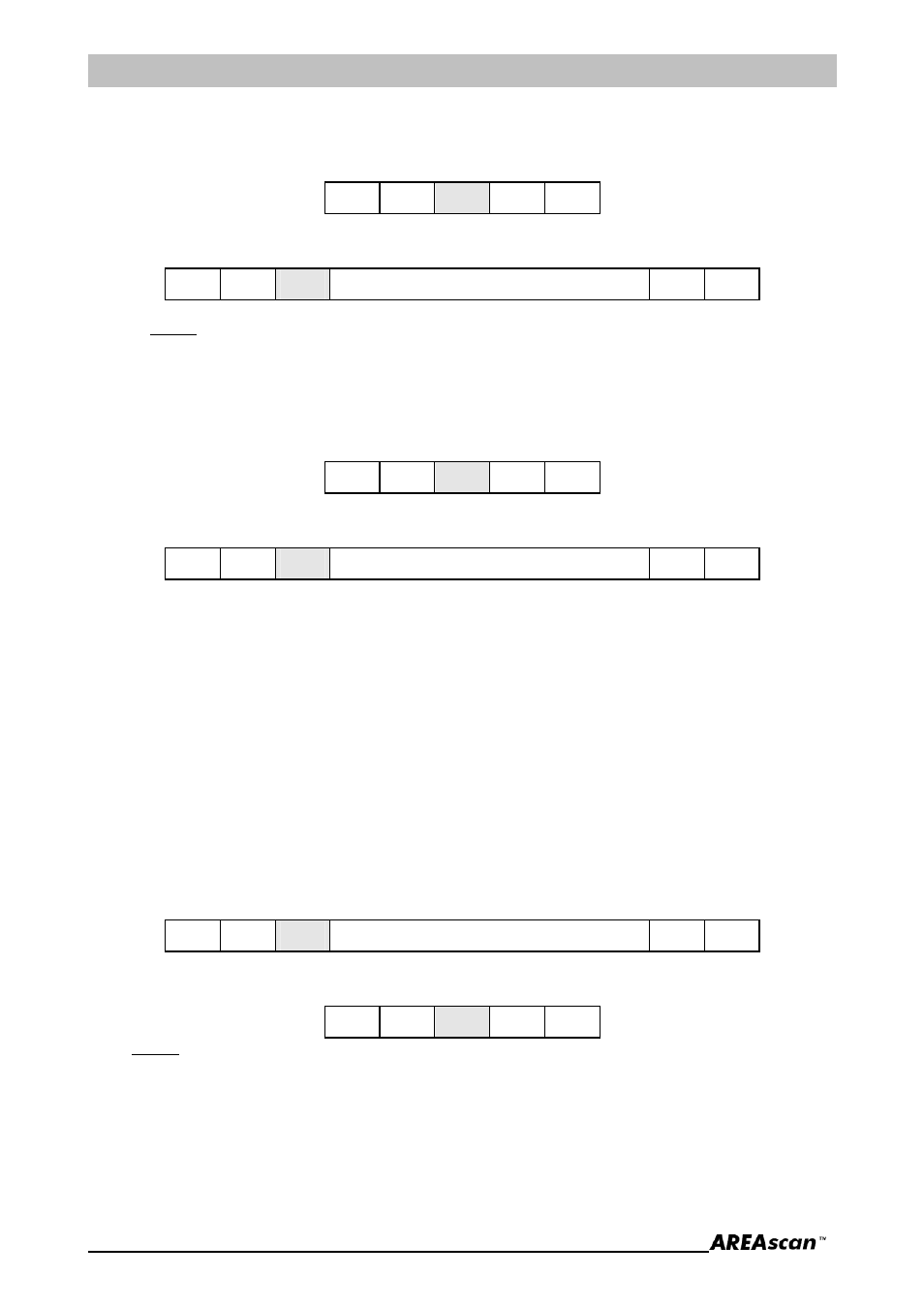
i. Firmware release reading command - 0x4B (ASCII ‘K’)
Reads the firmware release.
Host sends:
0x02 0x01 0x4B
0x03 0xB3
DS2 replies:
0x02 0x0B 0x6B
vvvvvvvvvv
0x03
x
where:
vvvvvvvvvv = 10 ASCII codes with the firmware version
x = checksum (complement to one of the Length, Type and Data field bytes sum)
j. Dip-switch reading command - 0x4C (ASCII ‘L’ )
Reads the dip-switch status.
Host sends:
0x02 0x01 0x4C
0x03 0xB2
DS2 replies:
0x02 0x02 0x6C
l
0x03
x
L = 1 byte with the local configuration status (Dip-switch)
bit 0 = OutDelay
4B - Output Delay (No Delay/100ms Delay)
bit 1 = OutMode
3B - Output Mode (NO/NC)
bit 2 = TeachMode 2B - Teach-in Mode (Absolute/Relative)
bit 3 = TeachEna
1B - Teach-in Active (Inactive/Active)
bit 4 = MeasAna
4A - Measurement Analysis Mode (BotTop/Total)
bit 5 = MeasRef
3A - Measurement Reference Beam (Bottom/Top)
bit 6 = SerMode
2A - Serial Output Mode (Binary/ASCII)
bit 7 = ProgMode
1A - Programming Mode (Local/Remote)
x = checksum (complement to one of the Length, Type and Data field bytes sum)
k. LEDs piloting command - 0x4D (‘M’ ASCII)
Turns on and/or turns off the panel LEDs.
Host sends:
0x02 0x04 0x4D
p f o
0x03
x
DS2 replies:
0x02 0x01 0x6D
0x03 0x91
where:
p = 1 byte with the Power LED status (0 off, 1 on)
f = 1 byte with the Failure LED status (0 off, 1 on)
o = 1 byte with Output LED status (0 off, 1 on)
x = checksum (complement to one of the Length, Type and Data field bytes sum)