IDEC DS2_Series User Manual
Page 29
DS2
series
Instruction
manual
28
Remote configuration from host user interface: synoptic table showing the output variation with
respect to the detection analysis mode configuration
Outputs
Function Mode
Analogue Switching Serial
ASCII
Complete
Beam
Status
Array
V=V
RES
*N
BEAM
[dark]
Binary
ASCII
Dark (default)
V=V
RES
*N
BEAM
[Top;
reference]
Top
Beam
Binary
ASCII
Top
Beam
Light
V=V
RES
*N
BEAM
[Top light;
reference]
Top Beam
(light)
Binary
ASCII
Dark (default)
V=V
RES
*N
BEAM
[Bottom;
reference]
Bottom
Beam
Binary
ASCII
Bottom
Beam
Light
V=V
RES
*N
BEAM
[Bottom
light; reference]
Bottom
Beam (light) Binary
ASCII
Dark (default)
V=V
RES
*N
BEAM
[0.5*(Top-
Bottom); reference]
Middle
Beam
Binary
ASCII
Middle
Beam
Light
V=V
RES
*N
BEAM
[0.5*(Top
light-Bottom light);
reference]
Middle
Beam (light) Binary
ASCII
Dark (default)
V=V
RES
*N
BEAM
[dark]
Total Beam
Binary
ASCII
Total
Beam
Light V=V
RES
*N
BEAM
[dark]
Total Beam
(light)
Binary
ASCII
Dark (default)
V=V
RES
*N
BEAM
[dark]
Total
Contiguous
Beam
Binary
ASCII
Total
Contiguous
Beam
Light V=V
RES
*N
BEAM
[dark]
Total
Contiguous
Beam (light) Binary
ASCII
Light Dark
(default)
V=V
RES
*N
BEAM
[dark]
N.
Transitions
Light Dark Binary
ASCII
Total
Beam
Dark Light V=V
RES
*N
BEAM
[dark]
N.
Transitions
Dark Light Binary
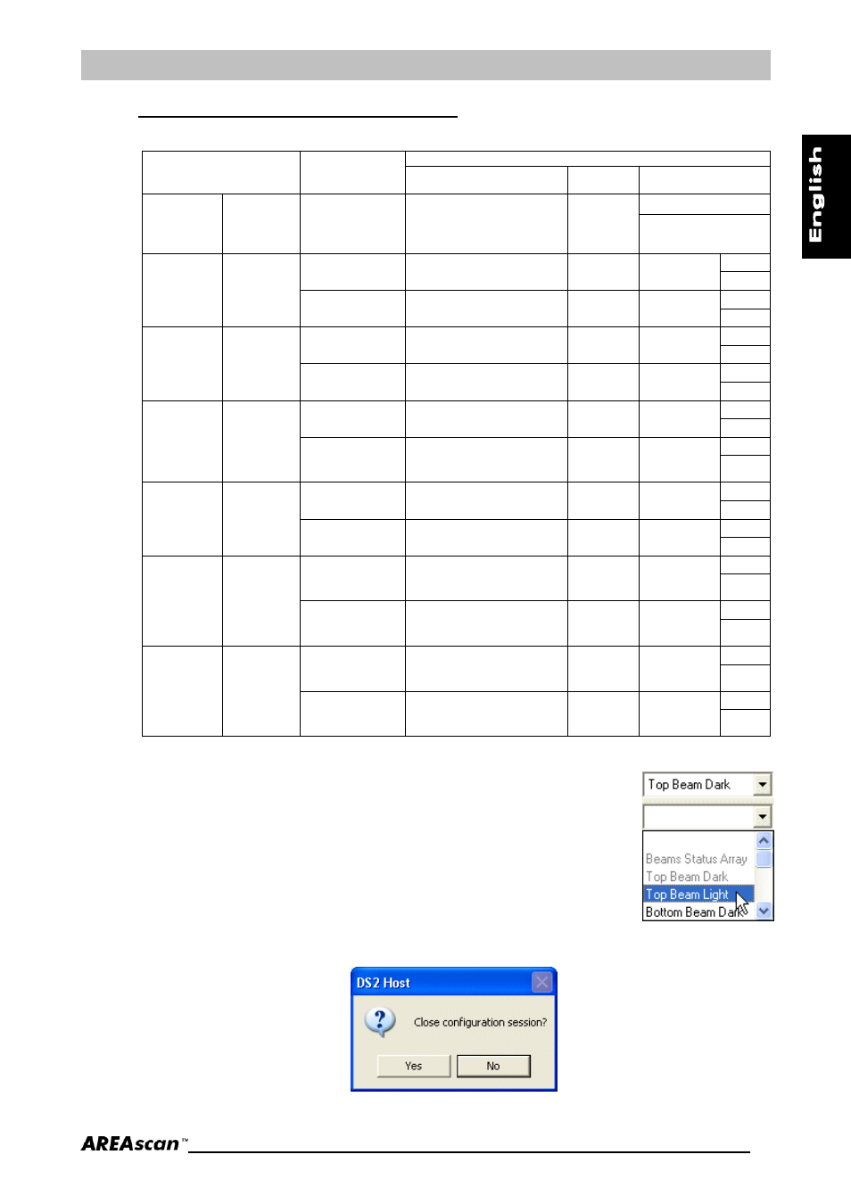
Some sections exclude each other (one or the other), i.e. if the Beam Status
Array has been chosen as measurement 1, all the items of measurement 2
are deactivated. Another example: if Top Beam Dark has been chosen as
the first measurement, the operator can choose any other measurement
excluding the same type as the first and Beams Status Array. The items not
admitted become grey.
The settings will be memorised in the DS2 non-volatile memory pressing
the Update button.
The graphic will be restored with the last shape stored in the DS2 memory
by selecting the Download button.
Press End to quit configuration session. The system will request the exit confirmation.