Modbus tcp server, Modbus tcp server -7, Modbus tcp server specifications -7 – IDEC MicroSmart Pentra User Manual
Page 95: Tcp c, Modbus tcp server specifications, Address map
W
EB
S
ERVER
CPU M
ODULE
U
SER
’
S
M
ANUAL
FC9Y-B1278
9-7
9: M
ODBUS
TCP C
OMMUNICATION
Modbus TCP Server
When the Web server CPU module is configured as the Modbus TCP server, Modbus TCP client devices can access and
communicate with the Web server CPU module.
When the Web server CPU module receives a valid request from a Modbus TCP client device, the data is read or written
according to the request received. The communication data received from Modbus TCP clients are processed at the END
processing.
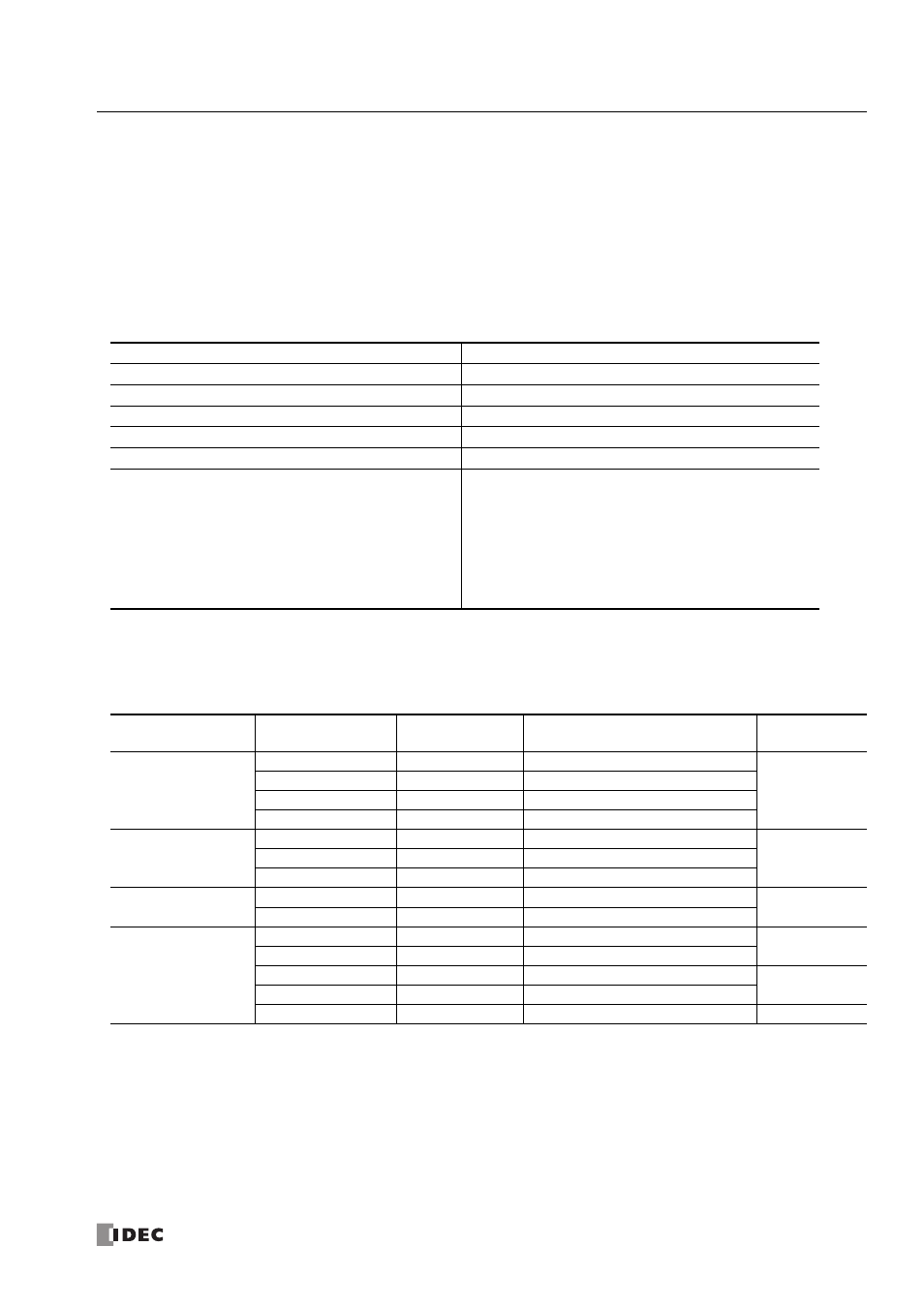
Modbus TCP Server Specifications
*1: When timeout occurs, the MicroSmart discards the received data and waits for the first frame of the next valid communication.
*2: The value when all server connections are configured as Modbus TCP server is indicated.
Address Map
*1: Addresses generally used for Modbus communication. For details about the calculation method of Modbus addresses for
MicroSmart devices, see chapter 12 of FC5A user’s manual basic volume.
Parameter
Modbus TCP Server
Slave Number
Ignored
Response Time
1.5 ms
Receive Timeout *1
500 ms
Number of Clients that can Access Simultaneously *2
8 maximum
Port Number
502 (can be changed between 0 and 65535)
Supported Function Code
01 Read Coil Status
02 Read Input Status
03 Read Holding Registers
04 Read Input Registers
05 Force Single Coil
06 Preset Single Register
15 Force Multiple oils
16 Preset Multiple Registers
Modbus Device
Name
Modbus Address
Map (Decimal)
*1
Communication
Frame Address
MicroSmart Device
Applicable
Function Code
Coil
(000000 and above)
000001 - 000504
0000 - 01F7
Q0 - Q627
1, 5, 15
000701 - 000956
02BC - 03BB
R0 - R255
001001 - 003048
03E8 - 07F7
M0 - M2557
009001 - 009256
2328 - 2427
M8000 - M8317
Input Relay
(100000 and above)
100001 - 100504
0000 - 01F7
I0 - I627
2
101001 - 101256
03E8 - 04E7
T0 - T255 (timer contact)
101501 - 101756
05DC - 06DB
C0 - C255 (counter contact)
Input Register
(300000 and above)
300001 - 300256
0000 - 00FF
T0 - T255 (timer current value)
4
300501 - 300756
01F4 - 02F3
C0 - C255 (counter current value)
Holding Register
(400000 and above)
400001 - 408000
0000 - 1F3F
D0 - D7999
3, 6, 16
408001 - 408500
1F40 - 2133
D8000 - D8499
409001 - 409256
2328 - 2427
T0 - T255 (timer preset value)
3
409501 - 409756
251C - 261B
C0 - C255 (counter preset value)
410001 - 450000
2710 -C34F
D10000 - D49999
3, 6, 16