Troubleshooting diagram 13 – IDEC MicroSmart Pentra User Manual
Page 146
13: T
ROUBLESHOOTING
13-20
W
EB
S
ERVER
CPU M
ODULE
U
SER
’
S
M
ANUAL
FC9Y-B1278
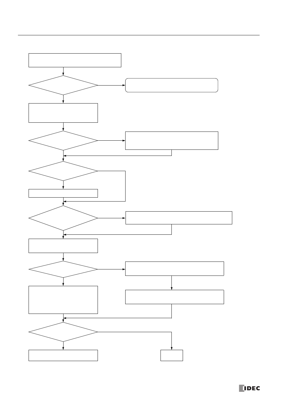
Troubleshooting Diagram 13
Turn off the power to the master station, and turn on the
power after a few seconds.
Is the error code 0
at all stations?
Is the communication
cable connected to the
RS485 port correctly?
Make sure of correct wiring. See "Data Link System Setup" of
the basic volume (page 11-2).
Turn off M8006 using WindLDR.
Check error codes for the troubled stations.
See "Data Link Communication Error Code"
of the basic volume (page 11-5).
For the master station, click the Initialize
Data Link button (see "Operating
Procedure for Data Link System" of the
basic volume (page 11-12)) or turn on
M8007 during operation using
WindLDR.
Are error codes
cleared to 0 at all
stations?
Clear the error codes at all stations using WindLDR. See
“Clearing Error Codes from WindLDR” on page 13-2.
Data link communication is impossible.
M8006: Data link communication prohibit flag
M8007: Data link communication initialize flag
Is data link selected for
port 2 correctly?
Is the PWR LED on?
See Troubleshooting Diagram 1,
“The PWR LED does not go on.”
Is M8006 on at the
master station?
Check port 2 settings using WindLDR.
See "Programming WindLDR" of the
basic volume (page 11-8).
Select data link for port 2 correctly and download the
user program again. See "Programming WindLDR" of
the basic volume (page 11-8).
YES
YES
YES
YES
YES
YES
NO
NO
NO
NO
NO
NO
Call IDEC for assistance.
END