35mmdin rail end plate – IAI America RCB-ISL-SIO User Manual
Page 3
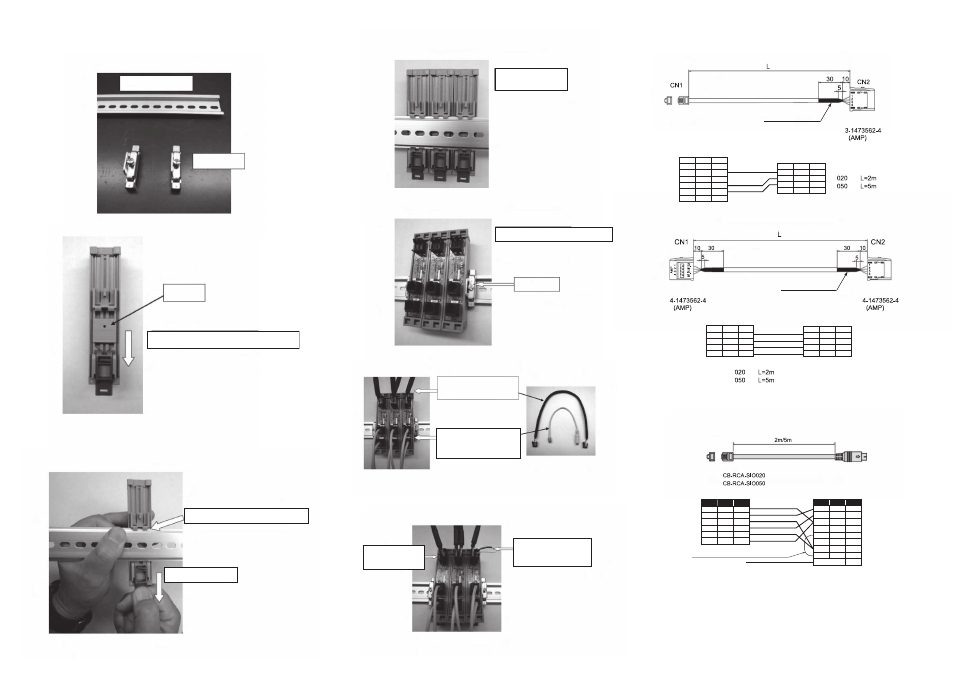
35mmDIN rail
End plate
Slider
Lower the slider to the lowermost position.
Pull down the pin.
Hook the DIN rail on the claw.
Rear side of
the RC-SIO isolator
Front side of the RC-SIO isolator.
End plate
Connect the adjacent isolators
using the isolator link cable
(CB-ISL-SIO
□□□
).
Connect the isolator with
the each axis controller using
the external machine communication
cable(CB-RCA-SIO
□□□
).
Insertion Port for
Communication Cable
on the Host Side.
Attach the attached terminal
resistance at the end of
the isolator link.
SGA
SGB
GND
1
2
3
4
5
6
BR
RD
-
GND
5V
5V
YW
OR
BL
GR
Color Signal
No.
(Cable Length 2m)
(Cable Length 5m)
YW
OR
BK
Color
Signal
No.
SGA
SGB
GND
1
2
3
4
BR / GR
RD / BL
5V
5
6
7
8
EMCS
EMCA
24V
EMGB
-
-
BK
Shield
FG
Short-Circuit Cable
ޓUL1007AWG2B(Black)
Shield Unconnected
No.
SGB
FG
1
2
3
4
WT
GND
SGA
Signal Color
YW
WT
BL
CN2
4-1473562-4
No.
SGB
FG
1
2
3
4
WT
GND
SGA
Signal
Color
YW
WT
BL
CN1
4-1473562-4
□□□
indicates the cable length L
e-Con connector
(Green)
e-Con connector
(Green)
Shrink Tube(Black)
7. Attachment and Wiring
(1) Procedure
① Because the RC-SIO isolator is attached onto the DIN rail, prepare the
following 35mm DIN rail and end plate.
② Lower the slider to the lowermost position on the rear side of the RC-SIO
isolator.
③ There is the DIN rail attachment section on the slider on the rear side of the
isolator. Hook the DIN rail on the upper claw in the attachment section as
shown in the picture and set the isolator onto the rail with the pin (spring type)
on the lower position on the attachment section pulled down. Then, finally,
release the pin to lock the isolator.
④ Using the same procedure, attach the required number of isolators onto the
DIN rail.
⑤ Fix the both ends of the attached RC-SIO isolators using the end plates.
⑥ Connect the cables.
⑦ Insert the terminal resistance.
(2) List of the Cables to be used
① Isolator Communication Cable CB-RCB-SIO□□□
② Isolator Link Cable CB-ISL-SIO□□□
③ External Machine Communication Cable CB-RCA-SIO□□□
No.
SGA
SGB
GND
1
2
3
4
5
6
-
-
-
GND
5V
5V
Signal Color
YW
OR
BL
No.
SGB
FG
1
2
3
4
-
GND
SGA
Signal Color
BL
OR
YW
□□□
indicates the cable length L
CN1
NTC-66R
CN2
3-1473562-4
e-Con connector
(Orange)
Shrink Tube(Black)