Harrington Hoists and Cranes MCR Trolley User Manual
Page 11
11
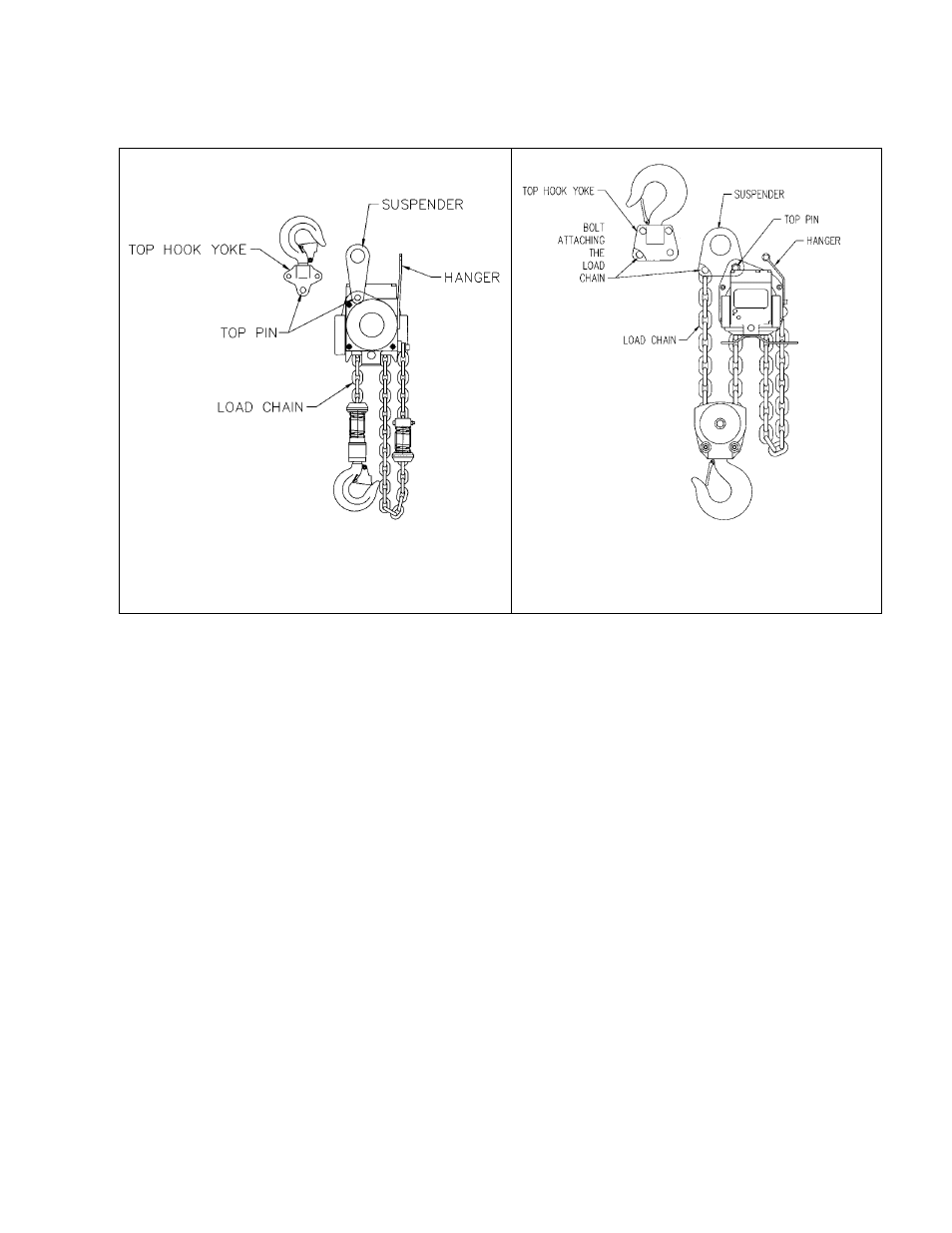
Figure 3-1
Installing Suspender on single fall hoists
TCR250P, 500P, 1000P and 3000P
Figure 3-2
Installing suspender on double fall hoists
TCR1000P2, 2000P2 and 6000P2
3.1.5 Trolley
Assembly
1)
Refer to
Figure 3-3
.
2)
Remove the Shaft Stopper Pin, Side Plate S (counterweight side), and Spacers from the Suspension
Shaft. Refer to
Table 3-1
.
3)
Insert the Suspension Shaft to Side Plate G (motor side) and attach it with the Suspension Shaft Bolt,
Slotted Nut and Split Pin (cotter pin). Refer to
Figure 3-4
and insure that correct Suspension Shaft
holes are used. Securely bend both branches of the Split Pin after insertion.
4)
Referring to
Figure 3-5,
Table 3-1
and
Table 3-2
install the inner adjusting Spacers and Suspender
(with hoist) on the Suspension Shaft. Use all of the Spacers provided with the trolley. If the beam width
is not listed in
Table 3-2
, use the next size smaller and make adjustments in accordance with
Section
3.1.6
.
5)
Place Side Plate S into the Suspension Shaft.
6)
Install the outer adjusting Spacers on the Suspension Shaft outside of Side Plate S. Insert the Shaft
Stopper Pin into Hole "A" so that Split Pin is to the left when seen from the front side of trolley switch
box. Temporarily install the split pin in the Shaft Stopper Pin and bend the split pin slightly to hold it in
place. The split pin should be fully bent after checking and attaining the proper beam flange
adjustment.