Danger – Harrington Hoists and Cranes SNER Hoist User Manual
Page 16
16
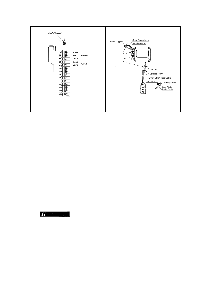
Figure 3-8
Pendant and Power Supply Cable
Hardwire Connections
Figure 3-9
Pendant and Power Supply
Cable Connections
Power Supply Cable - Installation
If the hoist is hook mounted to a fixed support ensure that the Power Supply Cable is properly
installed and supported between the hoist and the electrical power supply.
If the host is installed on a manual trolley, then the Power Supply Cable must be installed along the
beam that the trolley runs on. For curved beams a special cable suspension system will be
needed, and this instruction does not apply. For straight beams install the Power Supply Cable as
follows:
Install a guide wire system parallel to the beam.
For a manual trolley the guide wire should be positioned slightly outside the hoist's Cable
Support as shown in
Figure 3-9
.
Use the Cable Trolleys supplied with the hoist to suspend the Power Supply Cable from the
guide wire. Space the Cable Trolleys every 5 feet.
3.5.6
Connection to Electrical Power Source - The white and black wires of the Power Supply Cable should
be connected to an Electric Power Disconnect Switch or Circuit Breaker. This connection should be
made so that the hoist is phased properly. Refer to
Section 3.6.11
for instructions on how to check for
correct power supply phase connection.
3.5.7
Fuse/Breaker Capacity -The hoist's power supply should be equipped with overcurrent protection such
as fuses, which should be selected for 110% to 120% of total listed full load amperage, and should be
dual element time-delay fuses. Refer to the motor nameplate for the full load amperage draw.
3.5.8
DANGER
Grounding - An improper or insufficient ground connection creates an electrical
shock hazard when touching any part of the hoist or trolley. In the Power Supply Cable the ground wire
will be either Green with Yellow stripe or solid Green. It should always be connected to a suitable
ground connection. Do not paint the trolley wheel running surfaces of the beam as this can affect
grounding.
3.5.9
Voltage Change/Voltage Reconnection – Reference drawing 61364 for a complete wiring diagram.
Note: When changing voltage from 115V to 230V, the location of the black jumper wire is
relocated from terminal 4 of the Mechanically Interlocked Contactor, to location 7A of the
Terminal Block. See Fig. 3-10